Hot search: 3KW electromag
Aluminum ingot
1T one belt tw
2T steel melt

First, product use
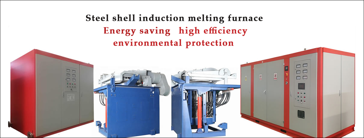
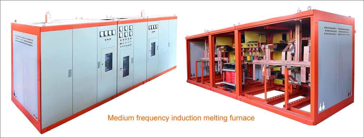
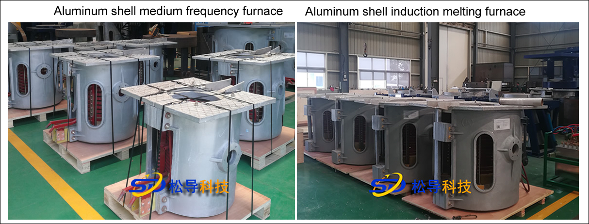
GWJ0.25-250/1 medium frequency induction melting furnace is an electric heating device that generates induction current in the charge of alternating electromagnetic field according to the principle of electromagnetic induction, so that the furnace material is heated and melted. The equipment is suitable for steel, cast iron and its alloy. Smelting.
Second, technical specifications and basic requirements
1. Technical specifications
Serial number | Project | Unit | Parameter | Remarks |
1 | Rated Capacity | t | 0.25 | |
2 | rated power | Kw | 250 | |
3 | Rated frequency | Hz | 1000 | |
4 | Operating temperature | ° C | 1650 | |
5 | Cooling water pressure | Mpa | 0.2 to 0.4 |
2. Basic requirements
2.1. The technical conditions of this product comply with the relevant provisions of GB10067.1-88 and GB10067.3-88 .
2.2. This product should work under the following conditions:
Altitude: < 1000 meters;
Ambient temperature: 5 ~ 40 °C;
Monthly average maximum relative humidity ≤ 90 %;
There are no conductive dust, explosive gases and corrosive gases that can seriously damage metal and insulating materials around the equipment;
No obvious vibration;
Water quality:
Hardness: CaO < 10mg equivalent;
Acidity and alkalinity: Ph=7 ~ 8.5 ;
Suspension solids < 10mg / L ;
Water resistance > 2.5K Ω;
Containing iron < 2mg .
Third, the structure is briefly described
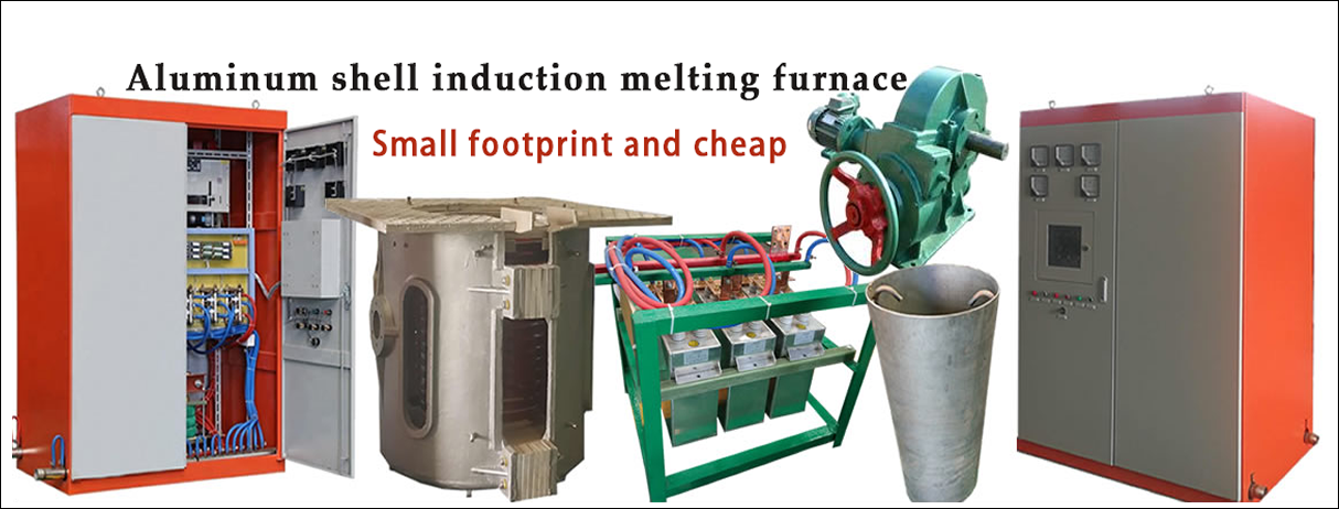
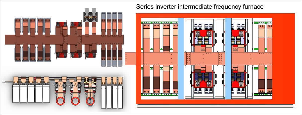
The equipment consists of a furnace body, a mechanical tilting device and an intermediate frequency power supply cabinet, a capacitor cabinet, a water-cooled cable, a water and electricity introduction system, and a control cabinet (or a control button box).
3.1. Furnace body
The furnace body is composed of an aluminum furnace shell, an inductor and a lining material. The aluminum furnace shell has the advantages of simple structure, light weight, no need for magnetic boring, and convenient installation. The inductor is wound with a rectangular cross section copper tube, and the copper tube is cooled by water. The upper and lower ends of the inductor are fixed on the asbestos cement board through the column, and the outer side is supported by a radial bolt, so that the inductor and the furnace shell become a stable whole.
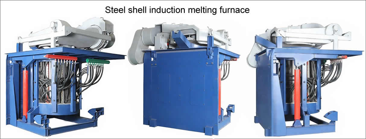
3.2. Tilting device
The furnace body is equipped with rotating shafts on both sides and is mounted on the sliding bearing housing. One end of the rotating shaft is coupled with the output shaft of the reducer, and the reducer drives the furnace body to tilt. The tilting angle can be arbitrarily controlled, generally not more than 95degrees. The reducer model is RZS-531A worm reducer, and the reducer motor power is 4Kw . Each furnace is equipped with a set of tilting device.
3.3. Hydropower introduction system
The current from the inductor is input through a water-cooled cable. Cooling water is supplied to both the inductor copper tube and the water-cooled cable. An electric contact pressure gauge is installed on the inlet branch of the inductor, and a bimetal thermometer is provided on the outlet branch for cooling water underpressure and over temperature alarm. The temperature rise of the cooling water is in accordance with the provisions of GB10067.1-88 : the inlet water temperature is ≤ 35 °C, and the temperature rise is ≤ 20 °C.
3.4. Operation cabinet
The operation cabinet is mainly used for the operation of the tilting furnace control, and is equipped with a button for controlling the forward and reverse rotation of the motor. According to the user's requirements and the situation on the spot, it is also possible to carry out the operation of the tilting control by moving the button box.
Fourth, the installation instructions
4.1. The installation of the equipment shall be carried out according to the floor plan and the basic drawing;
4.2. After installation, first check whether the grounding of the hob is good, and the grounding resistance should be less than 4 Ω;
4.3. Check the insulation resistance between the conductive plate of the inductor and the metal of the furnace before passing water: measured by 2500V megger, it should be greater than 2M Ω;
4.4. Connect the cooling water inlet and outlet pipes, and set the temperature control point of the bimetal thermometer to 55 °C;
4.5. Check the electrical control circuit of the reducer, tilt the furnace after error, and check whether the drive is flexible and normal;
4.6. No-load transmission to induction, the voltage from bottom to high to the rated value, inspection of components and sensor vibration;
4.7. After the above checks are correct, the mold can be hung from the mold to start the furnace.
5. Tanning and sintering of the furnace lining (reference when using quartz sand lining)
5.1. Tanning and sintering of the lining is the key to determining its longevity and safe operation, and the operating procedures should be strictly observed;
5.2. Requirements for lining materials
Quartz sand sintered with acid sand lining, quartz sand should be pure ( SiO2 > 98.5 ~ 99.5 %), no other inclusions, should be hand-selected, magnetically selected, sieved, baked at 180 ~ 200 °C for 5 ~ 6 hours dry;
5.3. Quartz sand particle size and ratio
The larger the granularity of quartz sand, the greater the tendency of expansion and cracking of the lining during the sintering process, but the coarse particles play a skeleton role in the lining, which can increase the strength of the lining. Taking into account the above two reasons, combined with the production practice experience, it is recommended to use 6 mesh for coarse particles .
The fine powder is easy to form a liquid phase with the additive during the sintering process, so it is required that the fine particles are sufficiently fine, and it is recommended that the fine particles are larger than
200 to 250 mesh.
Due to the different roles played by coarse and fine particles, in order to obtain a dense furnace lining body, according to the production practice experience, the following ratios are recommended for reference only.
Quartz sand ratio:
Particle size | 6 to 8 | 10 to 20 | 40 to 70 | 70 to 140 | > 200 |
proportion(%) | 30 | 25 | 10 | 10 | 25 |
5.4. Boric acid addition amount
The addition of boric acid not only lowers the temperature at which the quartz sand forms a liquid phase, but also reduces the viscosity of the liquid phase, so that the lining can be sintered at a lower temperature and can sufficiently fill the crack generated by the lattice transformation during the sintering process. However, boric acid can reduce the high temperature strength of the lining. Therefore, under the premise of satisfying the sintering, the amount of boric acid added should be minimized.
According to the above principles and production practices, the amount of boric acid added to each part of the lining is proposed for reference only.
The proportion of boric acid added to quartz sand:
Hot metal temperature (°C) | 1450 | 1500 | 1550 |
Within 100mm of the furnace bottom (%) | 1.0 to 1.2 | 1.0 | 0.8 |
The remaining part of the furnace bottom and the furnace (%) | 1.6 to 1.8 | 1.3 to 1.5 | 0.9 to 1.2 |
Furnace mouth (above molten iron liquidus) (%) | 2.2 | 2.0 | 2.0 |
5.5. Preparation of lining materials
After the dried quartz sand is prepared according to the specified ratio, fully stir it first, then add boric acid (boric acid is sieved through a 0.5 mm sieve), and then mix well, the mixed material should not be placed. For too long, to prevent moisture, it is best to use with the mix.
5.6. Knotting of the lining
5.6.1. Before knotting, firstly lay a layer of mica board with a thickness of 5 ~ 10mm on the inner wall of the sensor , and then lay a layer of asbestos board with a thickness of 10mm . (If the refractory mortar has been applied in the sensor, no mica is needed. Board, only asbestos board).
5.6.2. Ramming tool should be dedicated tamper layered, the thickness of each layer is added to 60 ~ 70mm is appropriate, after each tamping layer, must draw knotted track surface, before the insertion of new material Knotting another layer
5.6.3. Firstly, the bottom part of the furnace is knotted. The thickness of the bottom of the furnace should be higher than the required thickness. Then, the upper part of the furnace is scraped off to expose the solid part of the knot, and then scraped to the required thickness, and the mold can be placed into the mold. Continue to knot the furnace wall.
5.7. Sintering of niobium
The oven is an important part of sintering the crucible and obtaining excellent high temperature performance. The sintering process is determined according to the polycrystalline transformation characteristics of the quartz sand and the sintering characteristics of the SiO2-B2O3 system and the furnace capacity.
In order to ensure the oven sintering process rules, the relationship between the change of the quartz sand - boric acid material oven heating process and the heating rate is given here for reference:
< 500 °C, mainly to exclude moisture, including the chemical water released by the conversion of boric acid to boric anhydride, the lining is in a state of fragility, water vapor is easy to pass, and can be heated quickly;
At 500 ~ 650 °C, boric acid begins to melt, low-temperature quartz rapidly transforms into high-temperature quartz, and the liquid phase begins to form. To ensure uniform distribution of boric acid, to avoid the sudden expansion of quartz transformation volume, affecting the lining structure, it should be slowly warmed up;
650 ~ 850 °C, there is no quartz conversion, the sintering has not been carried out significantly, only need to consider part of the temperature uniform, can heat up faster;
850 ~ 1250 °C, high-temperature quartz began to transform into tridymite, but not intense, sintering has been carried out significantly, affecting the lining structure, should reduce the heating rate;
> 1250 °C, high temperature quartz is strongly converted into tridymite, the tendency of expansion and cracking is very large, and should be slowly heated.
In order to achieve the purpose of controlling the temperature rise, the input power must be strictly controlled. During the power transmission and sintering process, the maximum operating voltage of the furnace should not exceed 70 % of the rated voltage . When the temperature of the furnace rises to 1000 ~ 1100°C, the charge is started. The specific process can be carried out with reference to the sintering curve provided by the manufacturer of the lining material.
Since the polycrystalline transformation of quartz is very slow, sintering is a long process. It is not enough to rely on the initial sintering in the pre-production oven. It should be scheduled for a period of time to supplement the sintering, that is, within the first one or two weeks after the new furnace is put into operation. Non-production shifts should meet the hot metal insulation at around 1350 °C.
Because the furnace lining is sintered in the metal liquid immersion, it needs to bear a large metal static pressure and agitating and scouring at the same time. Especially the stirring and scouring of the molten metal is very harmful to the lining, so the power transmission to the new lining should be strictly controlled, try to Reduce the agitation intensity. It is recommended that the operating voltage of the first 2 to 3 furnaces be no more than 80 to 90 % of the rated voltage .
Sixth, use and maintenance
6.1. The tilting of the furnace body is done by operating the cabinet or moving the button box. Press and hold the "L" button, the furnace body will rotate forward, and the furnace mouth will be lowered to allow the molten metal to pour out from the mouth of the furnace. When the button is released, the furnace will remain in the original tilt state, so the furnace body can be rotated to stay at any position. Press and hold the "down" button and the furnace will rotate backwards until the button is released in the horizontal position.
In addition, there is an “Emergency Stop” button, in case the “Lift” or “Lower” button is pressed and then released, the button can not be automatically bounced back, immediately press the “Emergency Stop” button to cut off the power. The furnace body stops rotating;
6.2. During smelting, there must be sufficient cooling water in the sensor. Always check whether the water pressure and water temperature of the inlet and outlet pipes are normal during smelting;
6.3. The cooling water pipe should be cleaned regularly with compressed air, and the compressed air pipe can be connected to the joint on the water inlet pipe. Shut off the water source before disassembling the pipe joint;
6.4. When the furnace is shut down in winter, it should be noted that there should be no residual water in the induction coil, and it must be blown off with compressed air to prevent the cracking sensor;
6.5. When installing the busbar, tighten the connecting bolts and check if the bolts are loose after opening the furnace;
6.6. After the furnace is opened, it is necessary to regularly check whether the joints and fastening bolts are loose. Pay more attention to the bolts that connect the conductive plates.
6.7. When the wall is etched, it should be repaired. The repair is divided into two cases: full repair and partial repair:
6.7.1. Comprehensive repair
Used when the wall is evenly etched to a thickness of about 70 mm .
The patching steps are as follows:
6.7.1.1. Scrape all slag adhering to the wall until a white sintered layer is exposed;
6.7.1.2. Place the same die as when the furnace was built , set the center and fix it on the upper edge;
. 6.7.1.3 according to the formula and method of operation provided by the 5.3, 5.4, 5.5 preparation of quartz sand;
6.7.1.4. Pour the prepared quartz sand between the crucible and the ram and construct it with φ 6 or φ 8 round steel;
6.7.1.5. After compaction, add the charge to the crucible and heat to 1000 °C, preferably for 3 hours before continuing to heat up to melt the charge.
6.7.2 Partial repair
Used when the partial wall thickness is less than 70mm or there is erosion cracking above the induction coil.
The patching steps are as follows:
6.7.2.1. scrape off the slag and deposits at the damage;
6.7.2.2. Fix the charge with steel plate, fill in the prepared quartz sand, and compact. Note that you should not let the steel plate move in real time;
If the etched part is inside the induction coil, a full repair method is still needed;
6.8. Regularly add lubricating oil to each lubricating part of the induction furnace;
Seven, random files
7.1. Product Certificate of Compliance;
7.2. Product supply list (according to the contract);
7.3. packing list;
7.4. Product instruction manual;
7.5. Electrical schematic and instruction manual;
7.6. Random supply drawings:
Floor plan and base plan (one copy);
a schematic diagram of the reducer electrical schematic;
a general diagram of the furnace body;
`Drawing a crucible mold;
Copyright© 2007-2013 NO.6 Electric Mall All Rights Reserved