Hot search: 3KW electromag
Aluminum forgi
1T one belt tw
15KW electroma

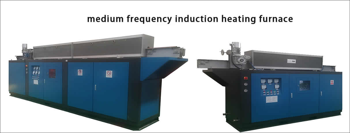
 Medium frequency induction heating copper tube annealing eq
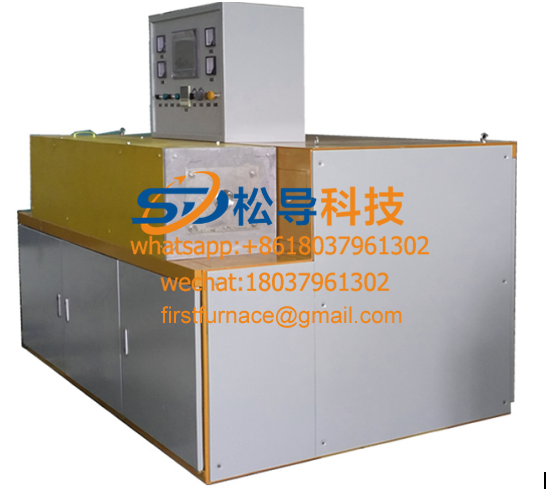 Medium frequency induction heating copper wire annealing equi
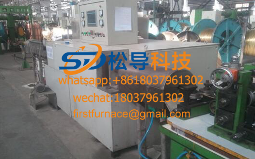 Copper hot rolling furnace
 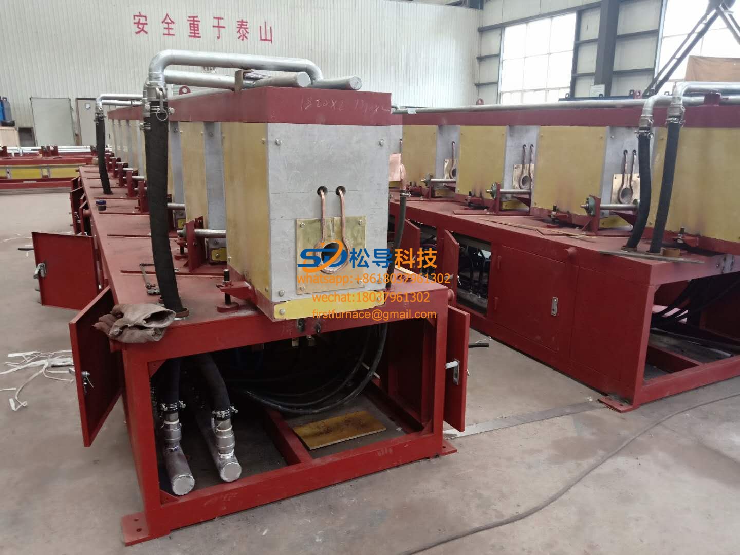 Copper tube medium frequency induction annealing furnace
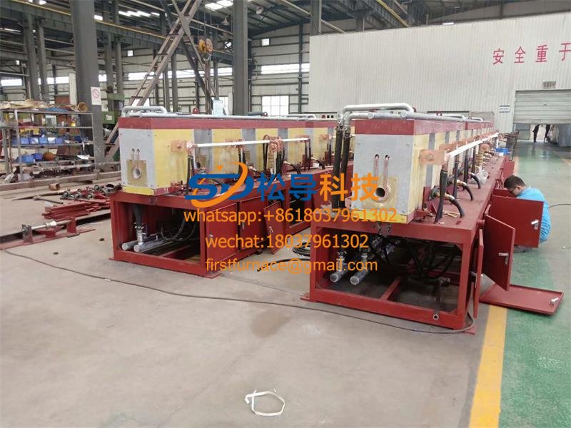 Copper tube annealing medium frequency induction equipment
 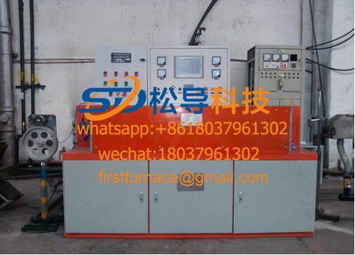 Copper tube annealing equipment
 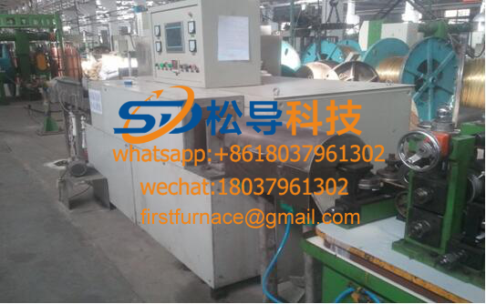 Copper tube annealing furnace
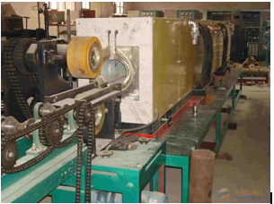 Copper pipe annealing
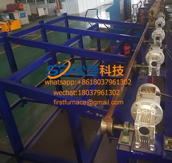 Copper tube heat treatment annealing equipment
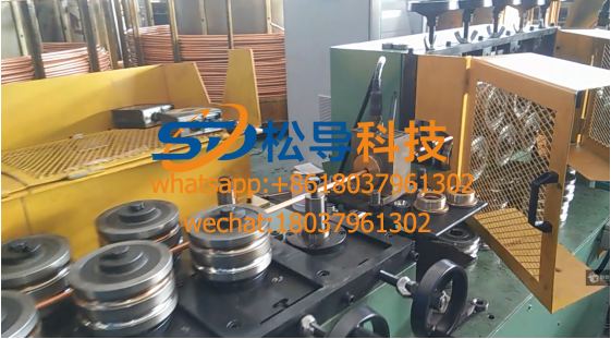 Copper tube induction heating continuous annealing production
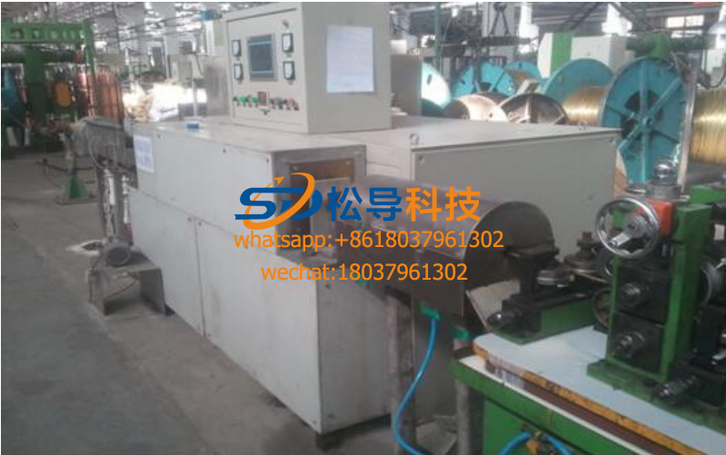 Copper tube induction continuous annealing furnace
 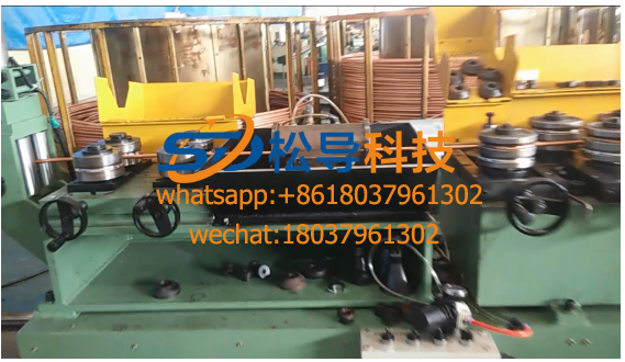 Copper Tube Induction Heating Continuous Annealing Furnace
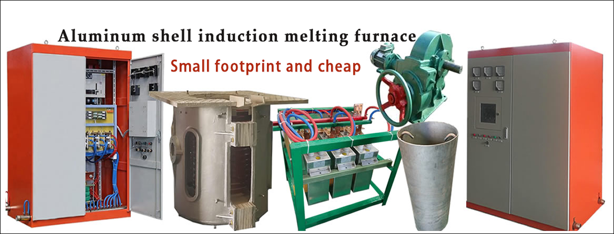
1. Overview:
Induction heating brass (brass) annealing equipment for brass (brass alloy outer sheath) with a line frequency induction heating annealing apparatus, and the hardness penetration depth according to the specific requirements of the customer, in order to achieve the removal of stresses and soften the brass alloy The purpose of the outer sheath .
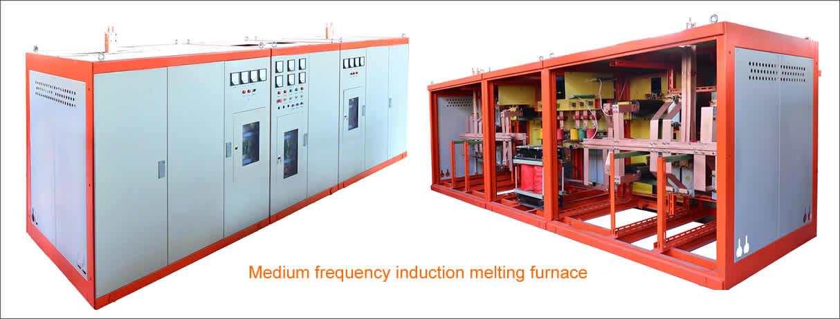
Equipment Introduction The complete set of equipment is designed and manufactured according to the mechatronic structure. The intermediate frequency power supply is a 6- pulse thyristor KGPS200KW/8KHZ intermediate frequency power supply, the load is a set of GTR series induction heating furnace, and the equipment is equipped with a set of reactive compensation capacitors. The device is designed with manual and automatic power adjustment knobs, which are automatically closed-loop temperature control. The external control console adopts PLC (Siemens) and touch screen control. It can easily input heating parameters on the touch screen, such as copper tube specifications, heating speed, annealing temperature, etc. After the parameter input, the IF power supply temperature closed-loop control system will automatically adjust the output power. Meet production needs. When a certain fault occurs in the production, the intermediate frequency power supply can be insulated according to the set temperature to avoid overburning the copper tube . The equipment is placed according to the user's requirements. Facing the equipment from left to right, the console is placed on the main equipment, which is convenient for the operator to observe the production situation and adjust the parameters conveniently.
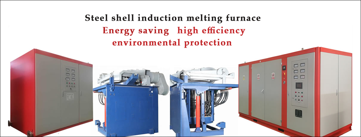
Safety protection The equipment has perfect safety protection measures, such as water shortage protection, phase loss protection, over current protection, over voltage protection, under voltage protection, high water temperature protection, etc., and sound and light alarm devices for faults. The equipment isconfigured in 200KW , leaving sufficient power margin to ensure continuous and stable production for 24 hours. All exposed conductors are installed in the locked electric control box with eye-catching safety warning signs, and no electrical safety accidents will occur. Each interlocking device can avoid damage to equipment or copper pipes caused by manual misoperation .
The equipment structure complete equipment covers an area of about 2000*1500mm and a center height of 1000mm . The power supply is integrated with the heating furnace body and is fixed by expansion bolts. The equipment is designed with an external operation console, which can be arranged according to the site conditions and is convenient for operation. The installation of the equipment is simple and quick. The user only needs to connect the inlet and outlet pipes to the inlet and outlet of the equipment (one nozzle for each inlet and outlet water), and the three-phase four-wire access device can be opened at the upper end.
, 2 , medium frequency induction heating copper tube annealing equipment
Technical Parameters
2.1 Material Technical Data
Workpiece material: through the ground wire (the inside is a copper stranded core conductor, and the outer surface is tightly covered with a brass alloy outer sheath)
Annealing method: online continuous induction heating
Material specifications: φ 6- φ 13mm , wall thickness 1mm
2 .2 main technical requirements for heating
Initial temperature: 20 °C;
Annealing temperature: Controllable and adjustable within 600 °C; Brass alloy layer temperature test accuracy ± 5 °C, induction heating temperature control accuracy is ± 20 °C.
Heating depth: 2mm ;
Process line speed: within 30m/min (maximum line speed is not higher than 30m/min );
The height of the production line is: 1m ;
2.3 Complete equipment technology selection
The complete set of equipment includes intermediate frequency power supply control system, far infrared optical fiber temperature measurement system, temperature closed loop control system, reactive compensation capacitor bank, induction heating annealing furnace body and so on.
IF power control system:
2.3.1 The intermediate frequency power supply is a thyristor frequency conversion device. The input voltage is 380V , 50Hz , and the output power is 200KW . The power can be adjusted manually or automatically according to the set temperature. The output frequency is 8KHz (frequency automatic tracking). The color of the cabinet is set according to user requirements. The outer dimensions are 2000 × 1500 × 1300mm and the center height is 1000mm .
2.3.2 Cartridge type combination silicon frame
The thyristor of the rectification and inverter part adopts the latest packaged combination silicon frame with patent application. This installation method makes the thyristor disassembly and assembly more convenient and scientific. When replacing the thyristor, just loosen it. A captive bolt can replace any thyristor component in the assembly. Moreover, this mounting method substantially reduces the volume of the thyristor assembly, which not only increases the operating space in the electrical cabinet, but also greatly reduces the line loss.
2.3.3 Large-capacity DC smoothing reactor
The smoothing reactor is very important for solid power and it has two functions. First, the output current of the rectifier is made smooth and stable. Second, when the inverter thyristor is short-circuited, the growth rate of the short-circuit current and the maximum short-circuit current are limited. If the parameter design of the filter reactor is unreasonable, the core material is not good or the manufacturing process is not good, which will have a great impact on the operational reliability of the intermediate frequency power supply.
2.3.4 Large-capacity thyristor
In order to ensure the reliability of the equipment operation, the rectification and inverter thyristors adopt the large-capacity KP and KK silicon of the Xiangfan platform to ensure the stable operation of the equipment.
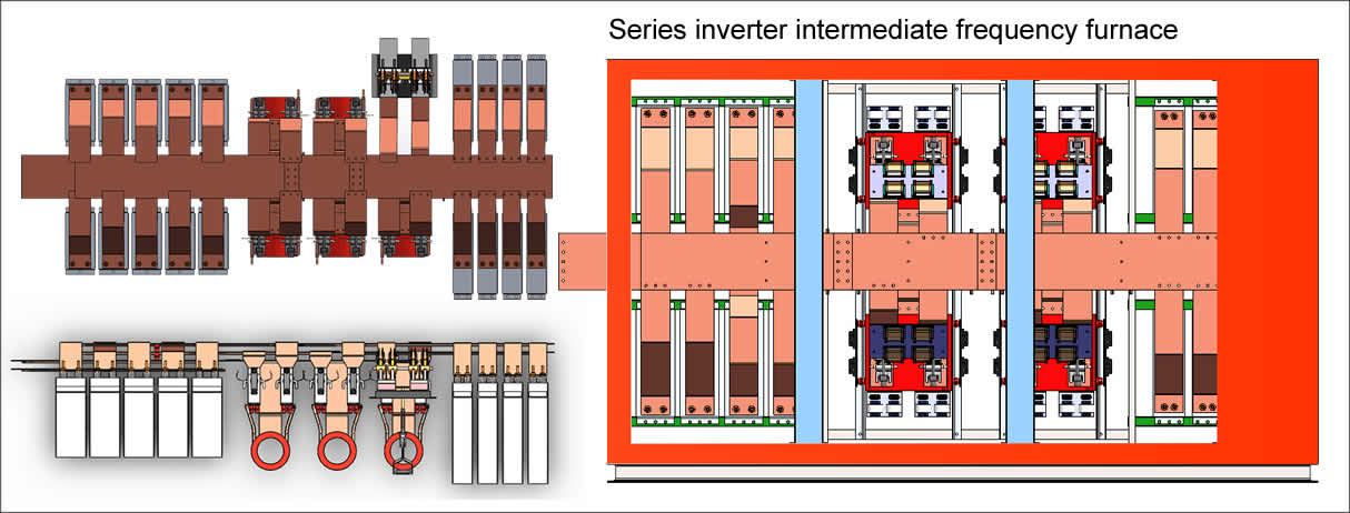
2.3.5 Use series and parallel compensation lines to reduce the loss of transmission lines
In order to reduce the loss on the intermediate frequency transmission line, the compensation capacitor of the inverter is connected in series and parallel doubling mode.
2.3.6 Main circuit parameters and component selection basis
The rated parameters of the main circuit of the intermediate frequency power supply are shown in the following table :
item Head | KGPS200/8 |
Input voltage ( V ) | 38 0 |
DC current ( A ) | 400 |
DC voltage ( V ) | 500 |
Induction coil operating voltage ( V ) | 750 |
Working frequency ( H z ) | 800 0 |
2.3. 6 medium frequency induction heating copper tube annealing equipment
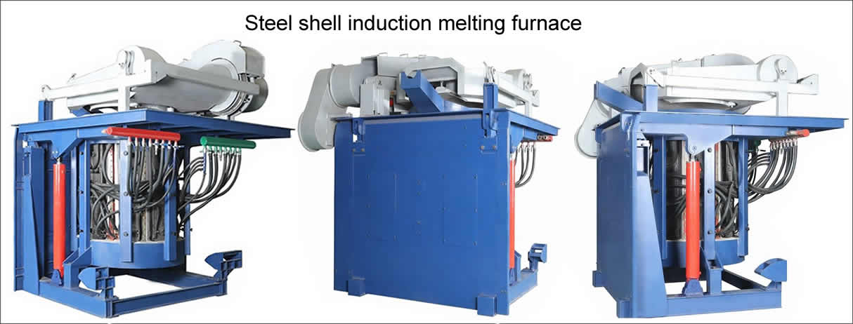
The inductor consists of a furnace casing, an induction coil, a stainless steel water collector and a furnace lining. The parameters of the induction coil combined with the annealed copper alloy tube are optimized with special computer software and combined with practical experience. It guarantees the best electromagnetic coupling efficiency at the same capacity. 99.99% of the induction coil T2 winding made of rectangular copper tube, the outer induction coil electrostatic spray process the insulating epoxy resin layer of high dielectric strength, greater than the withstand voltage of the insulating layer 5000V.
The inner layer of the induction coil is lined with white corundum furnace. The outer layer of the induction lining and the coil are fixed by refractory cement (US United Mine), which can play the role of insulation and heat preservation, and further increase the strength of the white corundum lining, effectively avoiding damage to the lining of the copper tube .
All inlet and outlet water of the sensor are collected into two stainless steel water collectors and connected to the total inlet and outlet pipes. The stainless steel water collector is beautiful and practical, which can effectively avoid the heat dissipation of the induction coil caused by the water pipe rust blocking the waterway.
Copyright© 2007-2013 NO.6 Electric Mall All Rights Reserved