Hot search: 3KW electromag
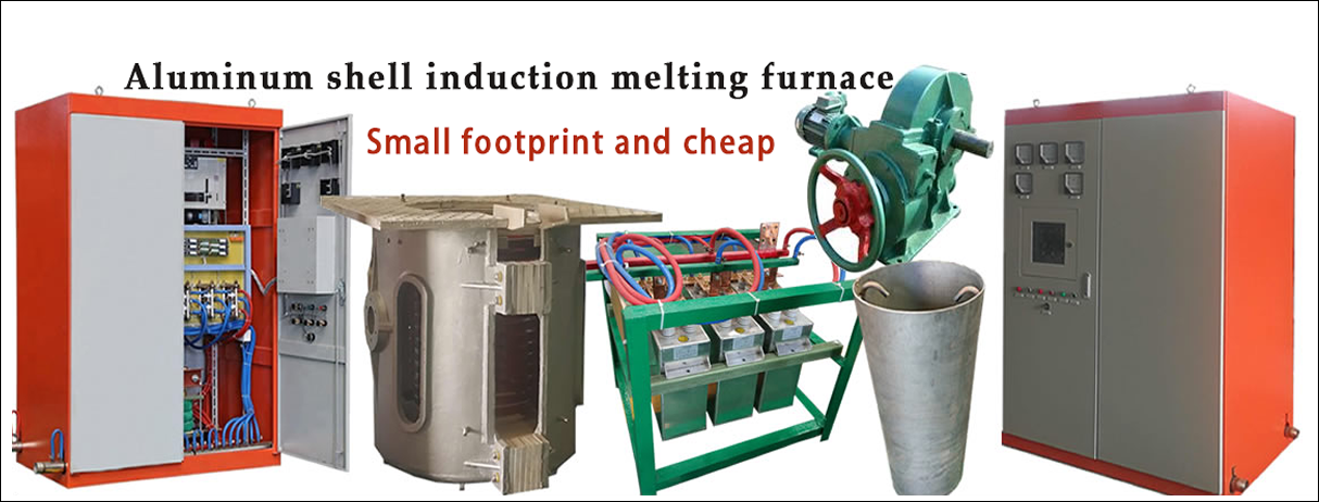
Aluminum ingot
1T one belt tw
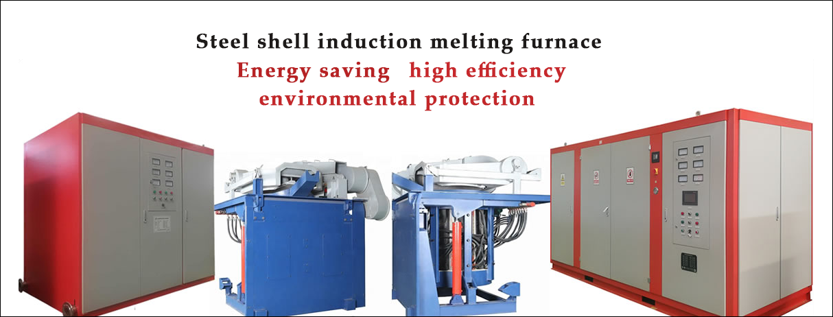
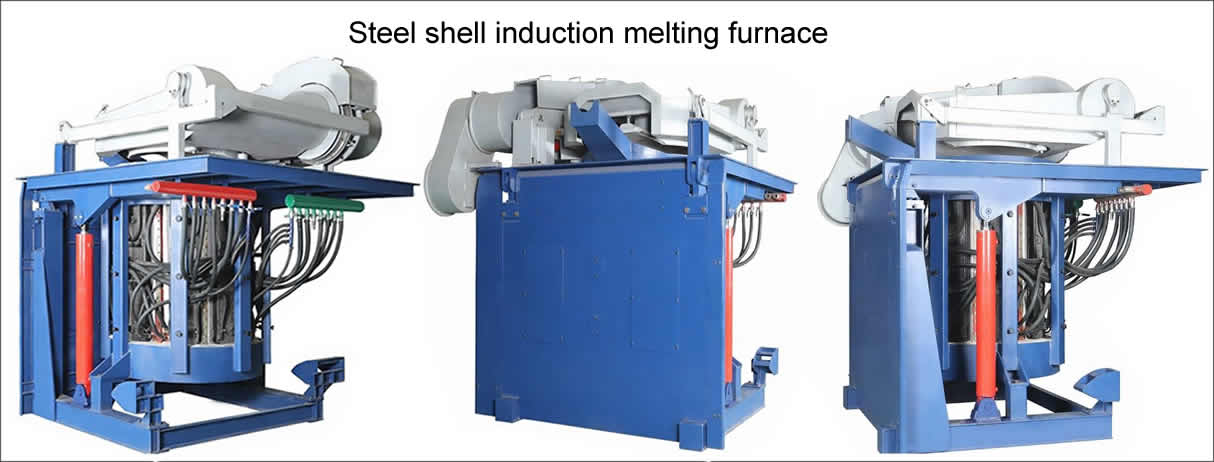
2T steel melt


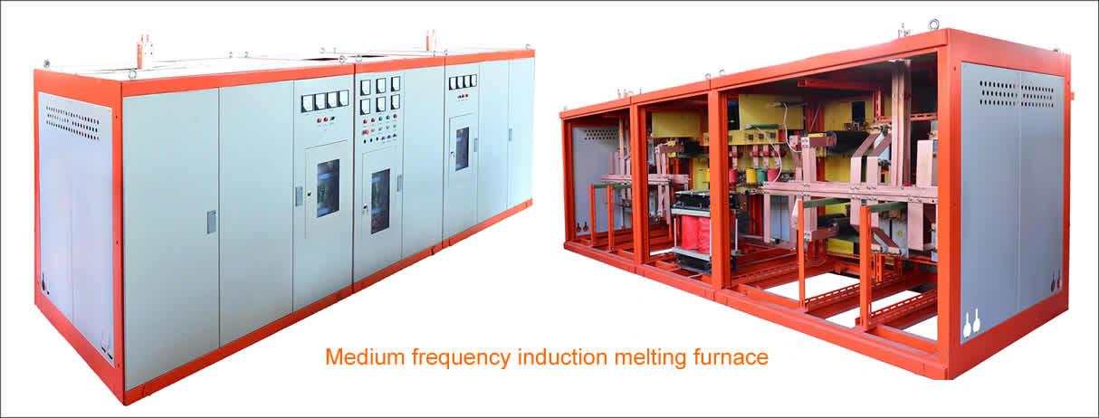
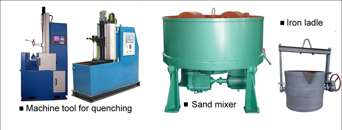
IF quenching machine mainly consists of a horizontal surface of the bed quench hardening, a pulse frequency power supply 6 KGPS- 250 KW / 2.5 KHZ frequency power supply, a frequency quenching transformer and inductor, PLC automatic control system.
The system has the characteristics of stable and reliable, precise control and complete protection functions. It can accurately control the surface of the heated workpiece to ensure that the surface quenching temperature and temperature difference after heating reach the required temperature range (± 25 °C).
It has a good man-machine interface, which can control the parameters such as temperature and speed of surface quenching during operation; display the parameters such as frequency, power, surface quenching heating temperature and speed of the power supply ; temperature rise of surface quenching , power supply Power distribution, etc. are set; parameters such as surface quenching various state parameters such as temperature batch number after heating are recorded and periodically sent to the management level.

I. Selection of process parameters for medium frequency quenching machine tools
Pre-quenching parameters:
Finished product diameter: Φ 114-229 mm, inner hole Φ 45-70 mm, tilt angle 3-4
Quenching ramp length: 2000-3600 mm arc radius R135-150mm
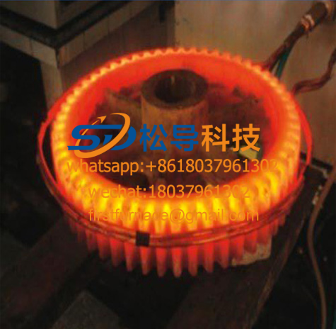
Hardening depth : 10-15mm Surface hardness: HRC= 45-50 Quenching temperature: 860 °C ± 20 °C;
Second, the main electrical parameters selection of medium frequency quenching machine tools
1. Main parameters of intermediate frequency power supply
Input voltage: 380V
DC voltage: 500V
DC current: 1600A
IF voltage: 1400V
IF frequency: 1000Hz ± 10%
IF power: 25 0KW/set
2. Capacitor cabinet parameters
2.5KZ Hz electric heating capacitor
Model: RFM 0.75 — 2 000 — 2.5 S
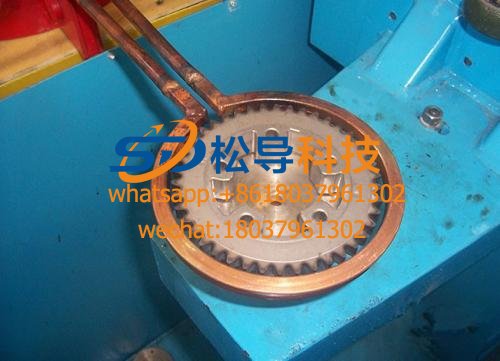
3. The sensor is: GTR- 2 00, the sensor is a flat heating sensor with a rectangular tube and a magnet .
4. Quenching transformer
In order to achieve the matching of the intermediate frequency resonance, a quenching transformer must be connected before heating the inductor.
The PR type quenching transformer is composed of a core and a primary secondary winding. The iron core is made up of 0.2-0.3mm thick high-magnetic imported silicon steel sheets (3K pieces). The iron core cooling adopts a water jacket type structure, and the transformer has strong overload capability, which is especially suitable for long-term continuous operation. The winding coils are wound in an overlapping manner, and the turns ratio is changed more, and the original paying side can be arbitrarily combined into odd-even ratios according to needs, and the load adaptability is strong. The specific parameters are as follows:
model | capacity | Matching intermediate frequency power | Primary side ratio | Secondary side ratio | Adaptive frequency |
PR- 1000 | 10 00KVA | 250 KW | 25~7 | 1 to 2 | 1~8KHz |
Third, surface quenching horizontal quenching bed selection
The bed body having a continuous quenching of CNC systems, segmented continuous quenching, quenching at the same time segment, while quenching functions for surface hardening of parts and the plane of the cylindrical surface.
The bed body has manual operation and fully automatic operation function . It is suitable for single and batch parts production . It is widely used in the field of induction heat treatment of tractors , automobiles , engineering machinery and bed industry . It has reasonable structure , complete functions andconvenient installation and debugging .
Bed by the bed main portion and a transmission system, the mask frame, NC electrical parts and other components.
( 1) Bed body part: The bed body adopts welded bed structure, and the whole body is subjected to stress relief annealing . The structure is reasonable , stable and reliable . The surface of the main exposed parts is specially treated and has good anti-rust and anti-corrosion properties .
(2) Transmission System: shaft driven by a stepper motor. It adopts frequency conversion speed regulation technology and adjusts speed according to process requirements, which can be adjusted steplessly.
(3) Part clamping adjustment mechanism: the use of special tools clamping parts, to achieve an accurate positioning and clamping the workpiece.
(4) block mask: the mask frame made of steel plate well, appearance, color and appearance both outer cooling water splashing is prevented, and easy handling and monitoring components quenching process...
( 5) Electrical control part : The electrical control part is composed of numerical control system , frequency converter , intermediate relay and programmable controller . The power supply line : 3 phase , 380V, 2.5Kw. It can store more than 20 kinds of parts. Quenching process , through the numerical control keyboard can program and store various programs . The bed is equipped with power failure protection , water shortage protection and other functions , with high safety and reliability .
First, the type of induction hardening machine:
The induction hardening machine is divided into high-frequency quenching machine and medium-frequency quenching machine according to the power supply equipment. According to the machine function, it can be divided into general quenching machine and special quenching machine.
The earliest quenching machine was modified from a metal cutting machine. There are three differences between the quenching machine and the metal cutting machine, that is, the load generated by the cutting metal, the electromagnetic field, the cooling of the quenching cooling medium and the electric appliance, and the inductor. Water requirements.
Second, the CNC system commonly used in quenching machine tools:
At present, there are many kinds of CNC systems at home and abroad, and their uses are not the same. The numerical control systems suitable for the characteristics of quenching machine tools are as follows: (1) Domestic economical numerical control system: This system programming is simple and easy to learn, easy to operate, and low in price. Resist the application of CNC universal quenching machine. However, there are some problems in the application of the system on the universal quenching machine: First, the system output and input interface are designed according to the functional requirements of the machine tool, especially the input interface is relatively small; the second is when there are two adjacent commands, 0.4s interval time, can not be sprayed immediately after the end of heating (for small workpieces generally require heating immediately after spraying); the third is to use a two-coordinate CNC system for lifting, one for rotation (division), double Simultaneous continuous movement of coordinates will affect each other, so the use of this economical numerical control system for general quenching machines requires necessary modifications.
(2) Foreign economical numerical control system: Foreign economical numerical control system has many brands and multiple models, among which Siemense 802 series is commonly used. This kind of system has the characteristics of perfect function, good performance, stable and reliable, high precision, large storage program, etc., but the price is high and the maintenance cost is high.
(3) Industrial control computer numerical control system: industrial control machine can be fully utilized in quenching machine tools PC hardware (such as 586, Pentium III) and software (such as DOS, Windows, Win98/Me, WindowNT/2000) resources integrate the latest control theory and network technology to achieve the most complex control and stronger software functions.
Third, the general quenching machine tool transmission methods are generally several? Which one is more stable?
According to the main transmission type, it can be divided into hydraulic type and full mechanical type. The hydraulic transmission has the advantages of simple structure, large driving force and fast moving speed (up to 150mm/S or more). There are shortcomings such as unstable moving speed and low positioning accuracy, and the hydraulically driven induction hardening machine is gradually eliminated. All mechanical transmissions are divided into T-type screw, ball screw, linear moving guide and other transmission forms. The all-mechanical transmission has the advantages of fast moving speed, high positioning accuracy, and easy shifting movement.
According to the mechanical structure of the moving part, it can be divided into two types: slide type and guide type. Skateboard type is the two-structured form with the largest number of applications in China. The bed is often made of aging-treated casting or welding structure. It has large bearing capacity and good stability. It can process large and heavy workpieces, and it has the widest application range. This form has the disadvantages of bulky bed, inflexible sliding, complicated rail processing and the like. The guide column structure is more common in Europe and the United States. The main advantage of this structure is that the machine tool is light in weight and flexible in movement. It is easy to realize the integrated design with the quenching liquid circulation cooling system, but it is not suitable for the processing of large and heavy workpieces. Large stability is poor (such as workpiece vibration).
4. When the quenching workpiece is scanned and quenched, how should the workpiece movement or the transformer sensor group move mode be selected?
Quenching machine tools generally have two transmission modes, one is that the workpiece moves and drives, and the other is that the workpiece moves up and down and the transformer sensor group moves up and down.
The selection of the two transmission methods mainly considers the following factors:
1) Considering the height (or length) of the entire quenching machine, when the length of the workpiece exceeds 2 m, the transformer sensor degree is generally selected for movement. Because of this design, the total height (or length) of the quenching machine can be lower (short). The total height of the scanning quenching machine is such that the workpiece is moved, which is generally more than 1 times the length of the workpiece scanning, compared to the two. Superiority is visible. Therefore, the small universal quenching machine, camshaft, half shaft, and steering rack quenching machine adopt the method that the workpiece moves and rotates, and the vertical quenching machine with the workpiece length exceeding 2 m moves the way of the transformer group.
2) Considering the shape and weight of the quenched workpiece, such as a large gear single-tooth scanning machine tool, the gear diameter is 6 m, the weight is 20 t, the quenching transformer and the inductor are small in volume and weight, and the transmission mode of the transformer sensor group is naturally adopted. Mobile is more convenient.
3) Special considerations, such as long and heavy rolls, but because the transformer sensor group is relatively heavy, the vibration during operation is very large, and the workpiece movement mode is still used at this time, and the transformer sensor is fixed.
4) In recent years, some induction heating companies in Germany have adopted a transformer sensor group moving structure for quenching machines with workpieces of 750-1500mm, which is the total height reduction of the quenching machine, and the Z-axis fast-forward speed is as large as 24m/s (400mm/ S)
5. How to choose the top speed of the quenching machine?
The selection of the rotational speed of the quenched workpiece during heating, from the heating uniformity of the workpiece, the faster the rotational speed, the smaller the temperature unevenness due to the uneven gap between the inductor and the workpiece. Early quenching machines generally set the speed range to 60-300/min. Some machines have step-variable speed shifts, while some machines use stepless speed change, which users can choose. However, some machines have extremely low speeds due to certain conditions. For example, the crankshaft neck rotary quenching machine has a spindle neck speed of 60r/min, and the connecting rod neck speed is 30r/min. This is because the connecting rod neck is rotated by the swinging mechanism (four connected rod structure) on the quenching machine. If the speed is too fast, the half-ring sensor cannot stably follow the journal, so it can only be rotated at a low speed of 30r/min. This speed is not suitable for the journal heating. The spindle neck is 60r/ Min is a simple reason for the design due to the use of a two-speed motor.
There is an argument that the selection of the rotational speed should be considered in the heating cycle of the workpiece. The rotation of the workpiece from a heating cycle should be no less than 10 times to ensure uniform temperature on the circumference of the workpiece. According to this calculation, the general induction heating time of the workpiece is often between 5-10s. If it is 5s to 10th, it is 120r/min, and 10s to 10th, the rotation speed is 60r/min.
With the development of induction heating speed, the heating cycle of the gear has been shortened to 0.1-0.2 s for the synchronous dual-frequency heating gear. Therefore, the workpiece rotation speed requirements are constantly increasing, and the maximum speed of some quenching machine spindles has reached 1,600 person/min. At present, the speed of the quenching machine reaches 600r/min. In addition, the workpiece rotation speed is also closely related to the cooling. For gears and spline shafts, the quenching cooling is usually carried out by means of a spray method. The workpiece rotation speed is too fast, and the quenching liquid is insufficiently cooled on one side of the teeth. Therefore, the speed of the quenching machine is still limited to 600r/min or 300r/min. In addition, it is necessary to develop mechanical or electrical components that can reduce the speed of the workpiece in time after the end of heating, so that the workpiece can be rotated quickly to achieve uniform heating purposes, and can be rotated slowly to achieve uniform cooling of the gear-like workpiece.
PREV:Horizontal CNC hardening machine
NEXT:No More Articles.
Copyright© 2007-2013 NO.6 Electric Mall All Rights Reserved