Hot search: 3KW electromag
Aluminum ingot
1T one belt tw
2T steel melt


 Tungsten-molybdenum intermediate frequency sintering furnace
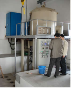 Medium frequency tungsten-molybdenum sintering furnaceMolybdenum wire molybdenum block sintering furnace
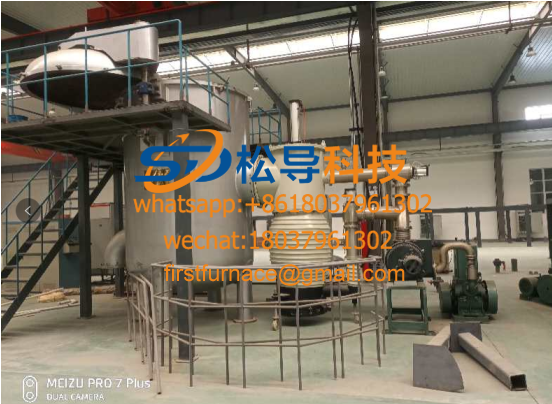 Medium frequency induction sintering furnace
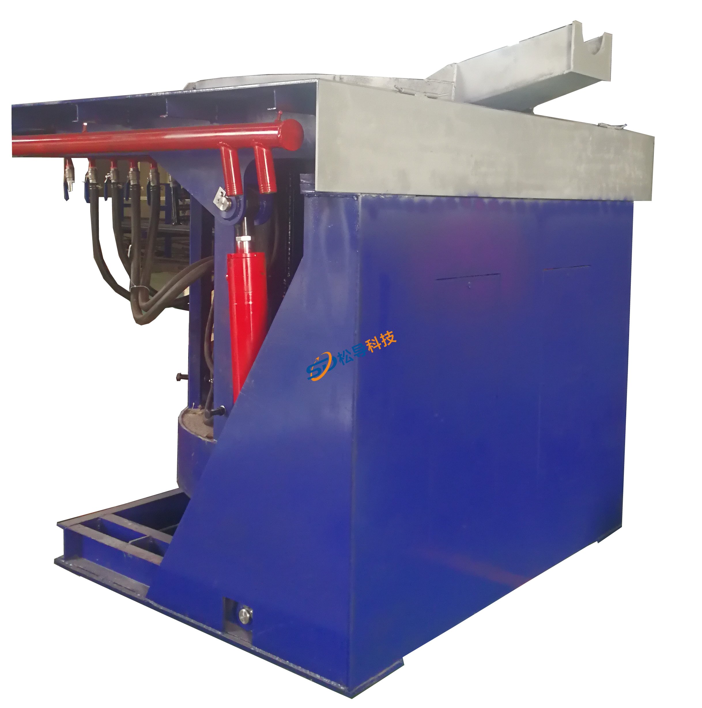 1T Medium Frequency Induction Furnace
 5T medium frequency induction furnace
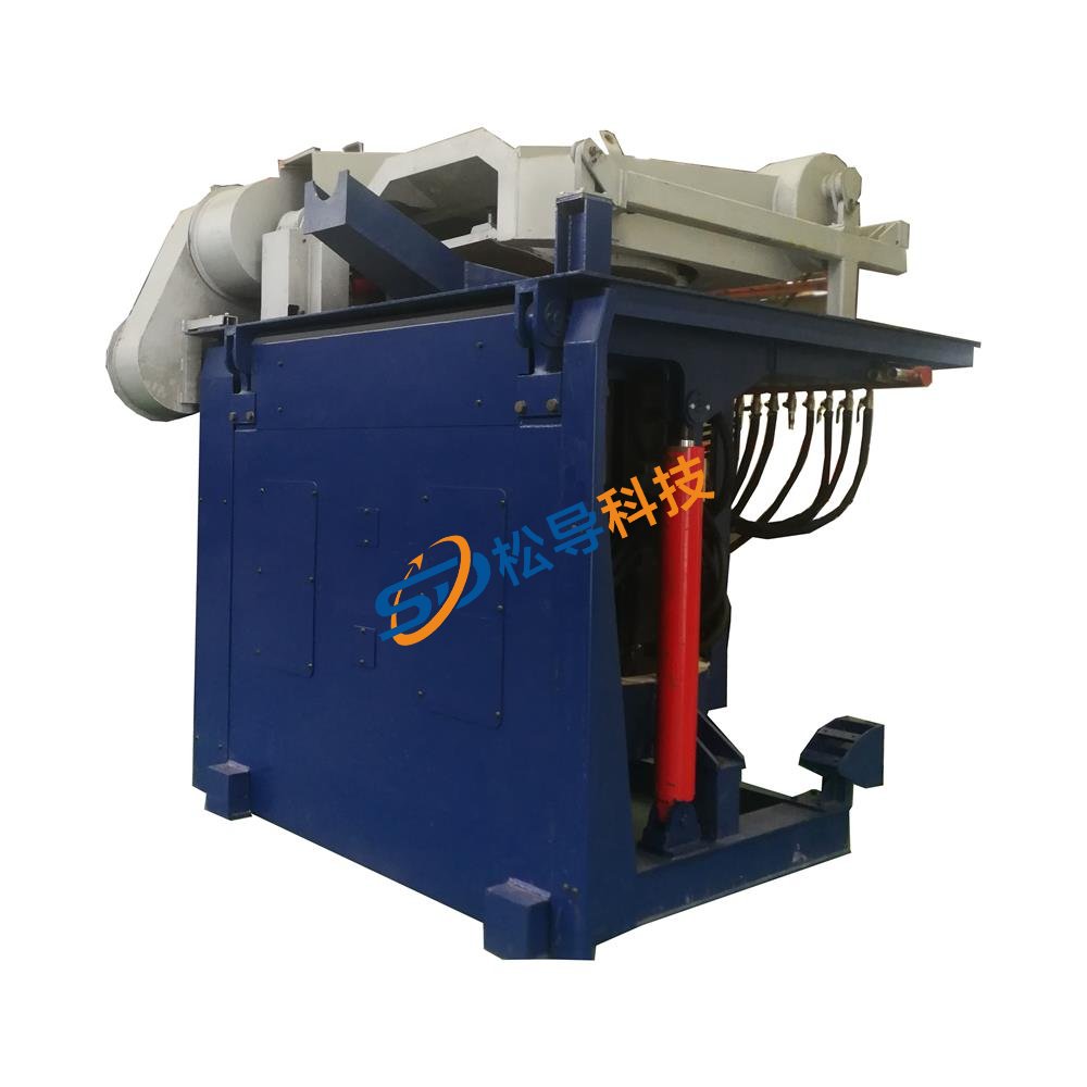 3T Medium Frequency Induction Furnace
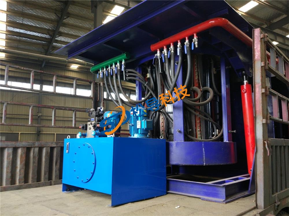 2T Medium Frequency Induction Furnace
 250 kg Medium Frequency Induction Furnace
 500kg Medium Frequency Induction Furnace
 Medium Frequency Induction Furnace
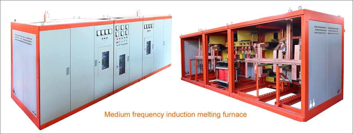
Molybdenum wire molybdenum block sintering furnace
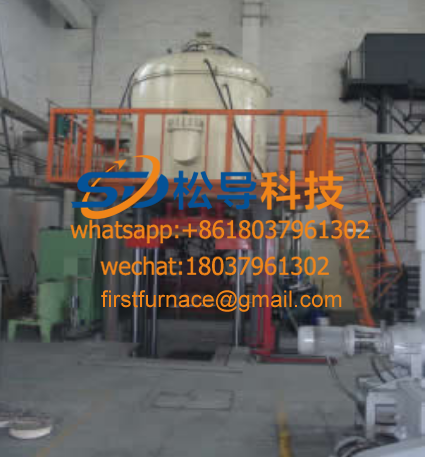
The molybdenum wire molybdenum block sintering furnace is mainly composed of a thyristor intermediate frequency power source, a hydrogen protection high temperature sintering furnace body, a temperature automatic control system, a mechanical pump vacuum system, various protection and advance (return) materials.
Molybdenum wire molybdenum block sintering furnace main technical indicators
Inner diameter: Φ 720 × 1600 thick 20
Internal helium material: tungsten
Sintering maximum temperature: 2350 °C
Working temperature: 2300 °C
Power supply voltage: 380V , 50Hz , three-phase four-wire system
Working frequency: 1200 ~ 1600Hz
Power supply: ≤ 600KW
Automatic temperature control, measurement, display, automatic recording
Gas protection in the furnace, adjustable flow, and slag discharge at the outlet
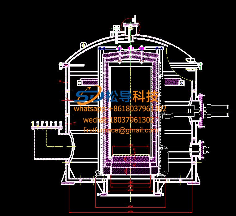
Main structure of molybdenum wire molybdenum block sintering furnace
1 , sensor
1.1 The effective height of the sensor design is 1728mm , which can effectively reduce the temperature unevenness at both ends caused by the magnetic field unevenness at both ends of the inductor, so that the temperature difference between the upper, middle and lower of the furnace center is within 15 °C. The inner diameter of the inductor is φ 960 , which is insulated and insulated from the tungsten sleeve by zirconia brick and corundum brick.
1.2 In order to reduce the tank current and reduce the loss of the inductor, the induction coil is designed to be boosted. That is, the coil voltage is twice the output voltage of the intermediate frequency power supply, and the coil current can be reduced by half.
1.3. The inductor coil is treated with epoxy insulation, and there is no discharge phenomenon between the turns.
1.4 Due to the large power of this set of equipment, in order to ensure that the inlet and outlet water temperature rises < 18 °C, the sensor outlet engine adopts four, so that the sensor water path is divided into two ways, effectively reducing the temperature rise of the induction coil inlet and outlet water, and increasing the engine. The reliability of the part.
1.5 Column using the coil to be insulated stainless steel column with a groove between the coil insulator, and a high voltage ignition carbonized epoxy avoided because the deposited metal column caused by dust, while increasing creepage distance between the coil turns.
1.6 The surface of the coil is sprayed with epoxy resin to prevent the deposition of metal dust and improve the insulation strength.
1.7 After winding pressure test 0.6Mpa / 30min ensure watertight coil.
A closed loop is added to the bottom of the 1. 8 coil to prevent the magnetic leakage from heating the bottom of the furnace shell and the corresponding components.
2 , heating body
The tungsten crucible heating element is used to heat the tungsten crucible by induction heating, and then the material to be heated is heated. The technical indicators reached by tungsten tweezers are as follows:
2.1 inner diameter: Φ 720 × 1600 thick 20
2.2 Density ≥ 83% TD .
2.3 Tungsten tube purity: Tungsten powder was sprayed with FWP-1 , purity > 99.9% .
3 refractory materials
3 .1 top: Since the feeding method is the lower feeding, the top refractory brick is made of four pieces of conical type, and the inner layer is made of zirconia with a refractoriness of 2600 °C as a refractory material. Since the outer layer has the heat insulating effect of zirconia as the refractory material and the temperature is low, the aluminum oxide (corundum) having a low refractoriness and a melting point of 2050 ° C is used as the refractory material. The center portion is provided with a circular hole for observation measurement and ventilation.
. 32 side insulation tiles:
The composition of the side brick: the refractory material between the inductor and the tungsten crucible is composed of aluminum oxide and zirconium oxide. Since the inner layer is close to the tungsten crucible and the temperature is high, the zirconia having arefractoriness of 2600 ° C is selected as the refractory material.
4. Furnace body
4.1. Furnace cover: The furnace cover is divided into two layers inside and outside, and the water is cooled in the middle. Bolted to the housing.
4.2 the lens cover: quartz glass lens, equipped with rotating baffles, to prevent contamination of the lens of the furnace fumes. When the temperature reaches 1200 °C, the baffle is opened, and the infrared thermometer measures and controls the workpiece in the furnace through quartz glass.
4.3 lens flange: equipped with the silicone rubber gasket and lid flange in contact with the quartz lens fixed to the upper flange, the lid is simply detached wing nut flange of the lens can be cleaned.
4.4. Air intake. The air inlet is provided at the upper end of the furnace cover to replace the air in the tank.
4.5. Temperature measuring bracket: Add infrared temperature measuring head, which can be adjusted and locked in three dimensions.
4.6. The furnace cover is provided with inlet / outlet ports, and the furnace cover is cooled by water.
4.7. Furnace shell: The shell is divided into two layers inside and outside, and the outer layer is welded by 10mm thick 1Cr18Ni9Ti with excellent welding performance. 1Cr18Ni9Ti 10mm thick inner layer is welded, reinforcing bars increases, the furnace liner to prevent excessive water pressure deformed the inner and outer layers, middle and bottom. The inner and outer layers are cooled by water and welded with a baffle so that the cooling water has no dead zone.
4.8. Armored thermocouple telescopic cylinder: The device is installed at the top cover of the furnace, through which the thermocouple is extended and pulled out, and the temperature of the infrared thermometer is converted. In addition, in order to facilitate the acceptance of the equipment, a thermocouple temperature measuring flange is also designed in the middle of the furnace side.
4.9. Blasting test port: Set the blasting test port at the position of the air outlet and the explosion vent to check the purity of hydrogen in the furnace.
4.10. Explosion-proof port: set the explosion-proof port and adopt spring compression method. When the pressure in the furnace is too large, the spring is opened to relieve the pressure in the furnace.
4.11. Sheathed thermocouple sealing means equipped with a silicone rubber strip, sealing flange.
4.12. Armored thermocouple protection tube: Built-in thermocouple.
4.13. The outlet of the conductive engine is insulated flange, and the conductive engine is taken out to seal with a silicone rubber seal. For easy installation and maintenance, the engine electrode flange is placed outside the furnace.
4.14. Vacuum outlet: The vacuum outlet is connected to the vacuum pump through a pipe (a vacuum pipe is added to the pipeline to reduce the vibration of the pipeline), and the tank is evacuated.
4.15. Induction coil: The stainless steel column of the induction coil is mounted on the bottom of the tank through an insulating plate.
4 . 16 . In order to prevent the top insulation material from slag and falling off, a molybdenum cover plate and a molybdenum cross bar are added at the bottom of the furnace roof insulation brick.
Safe use method of molybdenum wire molybdenum block sintering furnace equipment
The workpiece is mounted on the furnace mat, and the lower furnace mouth is sealed after the material is raised. Close all intake and exhaust valves, start the vacuum pump, pump the furnace to 10Pa , stop the vacuum pump, open the hydrogen filling valve, and when it ischarged to 1.02atm , open the hydrogen exhaust valve. After the explosion test is passed, the electric ignition is ignited and eliminated. Hydrogen (exhaust pressure is automatically adjusted to 1.0003 to 1.0008atm ). The hydrogen is continuously discharged and the furnace is sintered according to the heating curve. After the completion of the power failure, when the furnace temperature drops to 200 °C, close the intake and exhaust valves, turn on the vacuum pump, and pump it to 10Pa . Open the bleed valve and fill the furnace with air to normal pressure, reduce material, discharge, and reload. The material is subjected to the next sintering cycle.
Copyright© 2007-2013 NO.6 Electric Mall All Rights Reserved