
Comparison of electrical principles of series intermediate frequency furnace and parallel intermediate frequency furnace
The intermediate frequency furnace is divided into two types according to the compensation form, and the parallel resonant type (current type) intermediate frequency furnace
And series resonant (voltage type) intermediate frequency furnace.

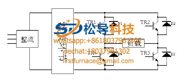
Figure 2.1 Main circuit diagram of the intermediate frequency furnace
The inverter used in the parallel resonant intermediate frequency furnace is a parallel resonant inverter whose load is a parallel resonant load. A current source is usually required to supply power. In induction heating, the current source is usually composed of a large inductance of the rectifier. Due to the large inductance value, it can be approximated that the current at the input of the inverter is fixed. By alternately turning on and off the controllable device on the inverter, an alternating square wave current can be obtained at the output of the inverter. The magnitude of the current depends on the current value of the input of the inverter, and the frequency depends on the device. On-off level.
The inverter used in the series resonant intermediate frequency furnace is a series resonant inverter whose load is a series resonant load. Usually, the voltage source is required to supply power. In induction heating, the voltage source is usually composed of a large capacitor and a rectifier. Due to the large capacitance value, it can be approximated that the voltage at the input of the inverter is fixed. Alternating the turn-on and turn-off of the controllable device on the inverter, the alternating square wave voltage can be obtained at the output of the inverter. The voltage amplitude depends on the input voltage value of the inverter, and the frequency depends on the device. On-off level.
The difference between a series resonant inverter and a parallel resonant inverter is different from the oscillating circuit used by them. The former is connected in series by L, R and C, and the latter is connected in parallel with L, R and C;
(1) The input voltage of the series resonant inverter is constant, the output current is approximately sinusoidal, and the output voltage is a rectangular wave. The commutation is performed after the current crosses zero on the thyristor, so the current always leads the voltage -φ angle.
The parallel resonant inverter has a constant input current, the output voltage is approximately sinusoidal, and the output current is a rectangular wave. The commutation is performed before the voltage across the resonant capacitor crosses zero, and the load current is always ahead of the voltage -φ angle. That is to say, both work in a capacitive load state.
(2) When the series resonant inverter is commutating, the thyristor is naturally turned off, and its current is gradually reduced to zero before the turn-off, so the turn-off time is short and the loss is small. When commutating, the turned-off thyristor is subjected to back pressure for a longer period of time.
When the parallel resonant inverter is commutating, the thyristor is forcibly turned off during full current operation. After the current is forced to fall to zero, a back pressure time is required, so that the turn-off time is longer. In contrast, series resonant inverters are more suitable for use in induction heating devices with higher operating frequencies.
(3) The series resonant inverter is easier to start, and is suitable for places where frequent starting work is required; and the parallel resonant inverter needs to add a starting circuit, which is difficult to start and has a long starting time. There are still people studying the starting problem of parallel resonant inverters.
The series resonant inverter thyristor temporarily loses the pulse, which stops the oscillation but does not cause the inverter to subvert. When the parallel resonant inverter thyristor occasionally loses the trigger pulse, it can still maintain oscillation.
(4) The series resonant inverter is connected to a large filter capacitor. When the inverter fails, the surge current is large and the protection is difficult. However, with the continuous improvement of protection means and the self-protection function of the device module itself, the protection of the series resonant inverter is no longer a problem.
The parallel resonant inverter is connected in series with the large reactor, but when the inverter fails, the current is limited by the large reactance, and the impact is not large, which is easy to protect.
(5) The voltage on the induction coil of the series resonant inverter and the voltage on the compensation capacitor are both Q times the output voltage of the resonant inverter. When the Q value changes, the voltage change is relatively large, so the adaptability to the load change is poor. The current flowing through the induction coil is equal to the output current of the resonant inverter.
The voltages on the induction coil and the compensation capacitor of the parallel resonant inverter are equal to the output voltage of the inverter, and the current flowing through them is Q times the inverter output current. When the inverter device is turned off, it will withstand a higher forward voltage, and the voltage parameters of the device are required to be higher.
(6) When the distance between the induction heating coil of the series resonant inverter and the inverter intermediate frequency furnace (including the compensation capacitor) is small, the influence on the output power is small. For parallel resonant inverters, the induction heating coil should be as close as possible to the intermediate frequency furnace (especially the compensation capacitor), otherwise the power output and efficiency will be greatly reduced.
Comprehensively comparing the advantages and disadvantages of series and parallel resonant inverters, it is decided to study the series resonant intermediate frequency furnace.
Copyright© 2007-2013 NO.6 Electric Mall All Rights Reserved
