Hot search: 3KW electromag
Aluminum forgi
1T one belt tw
15KW electroma


 Rolling mill detailed introduction
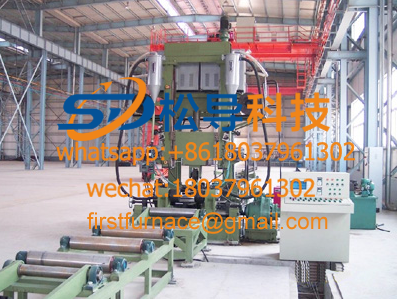 Steel production line detailed introduction
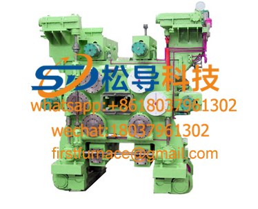 Universal mill detailed introduction
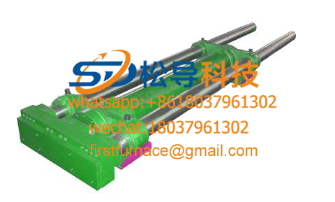 Pusher detailing
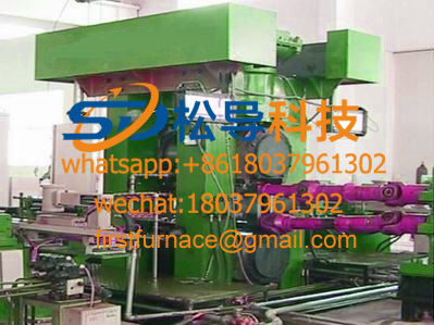 Four-roll mill detailed introduction
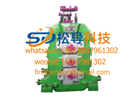 Three-roll mill detailed introduction
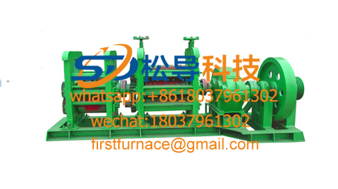 Hot rolling mill detailed introduction
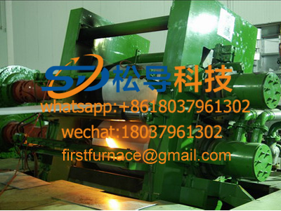 Aluminum casting mill detailsAluminum magnesium silicon alloy rod continuous casting and r
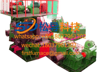 Six-roll cold rolling mill
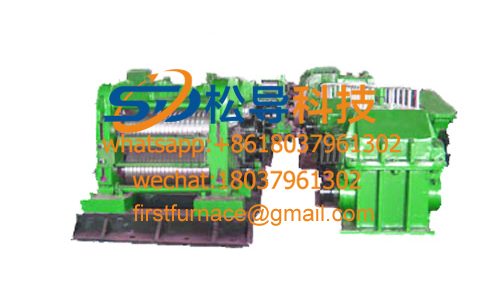 Continuous rolling mill
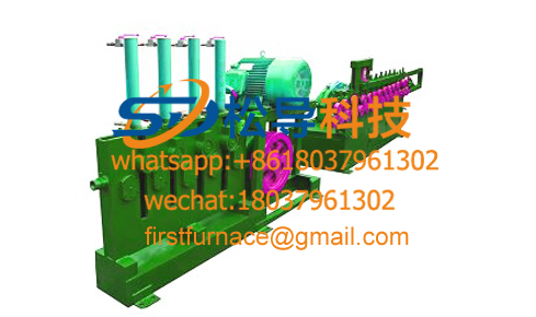 Cold rolled rebar equipment details
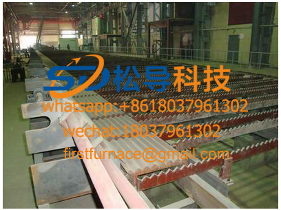 Detailed introduction of cold rolling steel
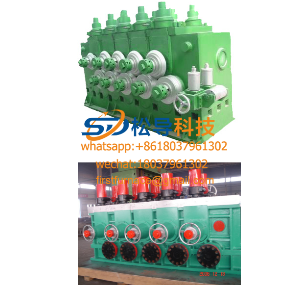 Straightening machine details
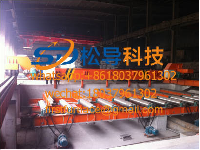 Roller table, lifting table details
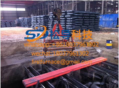 Billet fixture
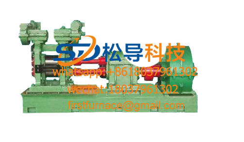 Two-roll cold rolling mill
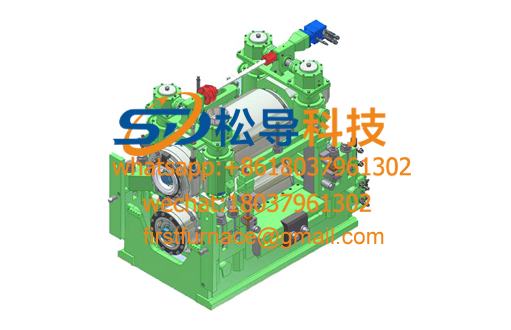 Short stress rolling mill detailed introduction
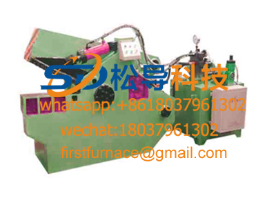 Fixed-length cutting machine detailed introduction
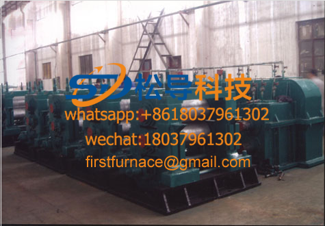
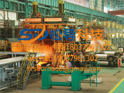 strip production line
One. Unit use
This production line process for the continuous casting and rolling, with production of electrical Pu aluminum alloy rod (aldrey and 8000 series alloys lever or the like), the finished rod diameter φ9.5mm, φ12mm, φ15mm.
II. The main equipment components
The production line mainly consists of 5T/H vertical high-efficiency energy-saving aluminum melting furnace, 10T belt weighing circular aluminum liquid holding furnace (with electromagnetic stirrer), online degassing filter system, four-wheel continuous casting machine (including pouring), Rolling shearing machine, active straightening device, frequency doubled induction heating device, continuous rolling mill system, aluminum alloy rod quenching device, double station aluminum rod forming device, continuous casting and rolling production line electrical control system, continuous rolling mill lubricating oil system, company Rolling mill emulsion circulation system and other components.
Aluminum alloy rod continuous casting and rolling production process
Raw material→melting furnace→preserving furnace→flow tank→casting→casting machine→oil pressure shearing (rolling shearing)→straightening machine→double frequency induction heating device→active feeding device→continuous rolling mill→quenching device→tracting device→ Continuous closing device (preform)→ Plum blossom closing device
IV. The main technical parameters
1). Crystallization wheel diameter: Φ1600mm
2). Ingot speed: 7.8-15.4m/min 3). Ingot section: 2400mm2
4). Casting machine motor: 4kw ( AC ) , 1000r.pm
5). Continuous rolling mill motor: Z4-355-32, 355kw, 600r/p/m
6). Final rolling speed: 4-6.2 m/s
7). Production (approx.): 2.7-4.2 t/h
. 8) rod diameter: φ9.5mm, Φ12mm, Φ15mm
9) the frame number: Total 15 (Y-frame 8 upload mover; the Y-shaped rack gear stage 7)
10). Hole type system: " Arc Triangle - Circle "
11). Roll nominal diameter: Φ255mm
12). Looping diameter: Φ2300mm
13). Take-up weight: about 1.5 - 2.0 tons / basket
V. equipment specification and composition
1 . Stove part
1.1 The composition of the furnace
1.1.1 5T/H vertical energy-saving aluminum melting furnace: 1 set
1.1.2 10T belt weighing round aluminum liquid holding furnace: 2 sets
1.1.3 Electromagnetic stirrer matched with 10T aluminum liquid holding furnace: 1 set
1.2 Overall description
5T/H vertical high-efficiency energy-saving aluminum melting furnace complete set of equipment, which uses clean energy such as natural gas as fuel, continuously melts aluminum ingot into aluminum water, and continuously produces and continuously refines through two holding furnaces. The preferred melting equipment for the casting and rolling system.
The vertical high-efficiency energy-saving aluminum melting furnace equipment is composed of a shaft furnace (cupola), a bottom furnace, a feeding system, a combustion system, a smoke exhausting system, an electric control system and the like.
Two sets of 10T belt weighing circular aluminum liquid holding furnace are composed of weighing sensor, circular furnace body, sealed furnace door, heat exchanger, ignition and combustion system, smoke exhaust system and control system.
Complete equipment aluminum ingot melted after the shaft furnace, by feeding into the bottom furnace heating system, is designed to melt the top 30004KW premix burner, a hearth furnace sidewall 1000KW burner design; Design of a hearth furnace slag door, The bottom furnace is designed with a rectangular aluminum liquid drain to keep the aluminum liquid working during melting smooth and convenient.
1.3 Equipment technical specifications
1.3.1 melting furnace
a. melting furnace type vertical cupola
b. Melting speed 5t/h
c. Start melting time ( from cold state to melting ) 0.5h
d. Feeding mode dumping
e. Feeding hoist capacity 2t
f. Use fuel natural gas
g. Equipment masonry inner diameter φ1500mm
h. Equipment net height 11m
i. Raw materials in bundles of aluminum ingots
j. Burner on the shaft furnace 3000KW
k. Shaft furnace bottom burner 1000KW
1.3.2 holding furnace
a. Holding furnace type round (2 sets )
b. Capacity 10T + 5%
c. burner 1 1000KW
d. furnace door structure sealing furnace door
e. Weighing form US AMCLL high temperature weighing module (including load cell and weighing module, high temperature wire and display, etc.)
1.3.3 Equipment Power
Melting furnace main fan: 18.5KW
Feeding frame motor 11KW
Holding furnace fan 7.5KW
1.4 Equipment structure characteristics
1.4.1 Shaft furnace feeding system
The shaft furnace charging system adds aluminum ingots or scrap aluminum wires to the melting furnace, and the feeder lifts the raw materials from the floor of the workshop to the feed port of the melting furnace.
a. Specifications:
specified load | 2.0T |
Cycle Time | 10-12min |
AC drive motor | 11KW |
1.4.2 shaft furnace
Of molten aluminum material, mainly composed of the bottom of the shaft furnace, feed port, chimney, lining and other parts.
The bottom of the furnace and the body of the furnace are made of high-quality steel plate and section steel. The bottom of the furnace is made of 12mm steel plate, and the middle is reinforced with channel steel, so that the whole furnace bottom can withstand the weight of 20 tons of aluminum ingot without deformation; the furnace body is made into a barrel with 10mm steel plate. The flange is made of 16mm steel plate, and a layer of aluminum silicate fiber blanket is placed on the furnace body, which can greatly reduce the temperature of the furnace wall. The high-alumina refractory brick is built in the middle. The innermost lining is directly in contact with flame and aluminum water. Masonry ensures the service life of the lining.
The feeding port is designed above the shaft furnace. This feeding method can make the aluminum plate piled up from the bottom of the furnace to the feeding port of the furnace body, prolonging the contact time between the flue gas generated by the burning of the burner and the aluminum ingot, so that the aluminum ingot can be maximized. The ground absorbs the residual heat of flue gas, increases the utilization efficiency of heat, and saves fuel cost. According to actual use, the gas consumption per ton of aluminum water is less than 55 cubic meters of natural gas in continuous state , which is only 1/2~1/3 of theopen hearth .
The burner is placed at the top of the furnace so that the aluminum material melts near the bottom of the furnace and the upper aluminum material is preheated by the combustion gases. The molten aluminum flows from the aluminum outlet to the bottom of the furnace. As the aluminum material melts, the aluminum material in the melting furnace moves downward, so that the molten aluminum liquid can be continuously supplied.
1.4.3 shaft furnace
Aluminum was used for the heating after melting, the molten aluminum is melted directly into the shaft furnace hearth furnace, taking into account the slagging of molten aluminum, the slope is increased beyond the mouth 500MM; rectangular furnace bottom, designed to burn a 1000KW The mouth is used for heating; the design of a slag door, the slag door adopts the hinge structure, and is used for the slag of the bottom furnace; the design of the rectangular aluminum water nozzle can store a certain aluminum liquid during normal melting, and can be drained when the furnace is stopped. Aluminum liquid.
a. Specification
Refractory thickness | ≥500mm |
burner | 2 sets |
AC fan motor | 15KW |
1.4.4 Premixed combustion system
Vertical energy efficient aluminum melting furnace complete system combustion system premixed combustion system, which ensures that all air and fuel are completely mixed into the burner, providing a more stable flame and more complete combustion.
The system consists of the following components: the fan air supply system, the fuel supply system, and the combustion control system.
1.4.4.1 . Fan air supply system
The system has a high-pressure fan for supplying air, and the air entering the fan needs to be filtered, and the gas composition should be stable. In order to prevent the suction phenomenon of the fan, an air butterfly valve is arranged at the air inlet of the fan to control the amount of air entering. The pressure of the exhaust gas of the fan is detected to prevent the pressure from being too high or too low. The maintenance of the fan is very important, because the fan fails during production, which has serious consequences.
1.4.4.2 . Fuel supply system
The fuel is natural gas, and the requirements for the system are pressure and steady flow. A smooth supply pressure is very important for the normal operation of the system, as its fluctuations often lead to instability in combustion. Therefore, the system has detailed requirements for pressure, and once it exceeds the standard, the system will automatically cut off. Since the fuel is in the form of a gas, many safety requirements are considered in the logic control.
1.4.5 Holding furnace system
It is used for heating, heat preservation, refining and standing of aluminum liquid before casting. 20t weighing type circular aluminum liquid holding furnace equipment consists of steady module, furnace steel structure, furnace lining refractory, furnace door and lifting mechanism, combustion system, smoke exhaust system, temperature measurement system, dust cover, electrical control system and other components Composition. Furnace holding furnace into a rectangular design, the volume of> 10T, design a 100 × 104 Kcal burner for heating; Design of a door, with vertical electric lift structure hearth furnace for slag refining; Design exhaust port One, an air preheater is designed above the exhaust port, and the preheated air is used as a combustion air to participate in the combustion of the bottom burner. The top of the furnace adopts a monolithic spherical dome structure to enhance the radiation effect; the contact part of the slag line with the aluminum liquid is integrally cast by the Tianjin Non-adhesive aluminum castable, the aluminum liquid has good quality and no slag; the aluminum inlet and the aluminum outlet The design is reasonable, and the upper part of the aluminum liquid is designed to measure the temperature of the burner according to the temperature of the aluminum liquid.
Furnace steel structure
The furnace wall is welded by 10mm thick steel plate (Q235-A) and section steel to strengthen the steel structure at key parts to prevent deformation. The steel frame bottom structure and the hanging roof are provided. The overall structure is specially designed for the casting and rolling production and process operation characteristics. It has been proved that the structure has good rigidity and strength.
The bottom of the furnace is made of 14MM steel plate and No. 16 channel steel. The magnetic window part is made of 16MM non-permeable stainless steel plate and strengthened with reinforcing ribs. It has good mechanical strength.
The top of the furnace consists of No. 16 I-beam. There are No. 10 channel steel and No. 10 I-beam in order to install the top hanging brick and metal hanging hook.
Refractory material:
The molten pool part is constructed with special high-aluminum bricks, which can effectively prevent the adhesion of aluminum and furnace lining to adapt to thermal expansion and contraction changes and anti-aluminum liquid leakage. At the same time, there is excellent insulation effect.
The side wall of the liquid level line above 300mm is composed of high-quality clay brick (or second-grade high-alumina brick), lightweight thermal insulation brick and ceramic fiber felt. The top is composed of high-quality refractory concrete, ceramic fiber felt and lightweight heat-insulating refractory concrete. On the stove top 300mm intervals arranged uniformly heat-resistant steel clamps fixed to the roof tile hanging steel.
Reasonable design of the slag angle of the furnace door ( designed at 25°) is convenient for slag slag operation.
For large and wide roof-shaped refractory furnace opening easy to crack, damage, paralysis collapse disadvantage, according to our experience in the production of construction for many years large molten aluminum holding furnace, the use of a number of design and construction of new technologies, such as the bottom "binning " Casting, furnace refractory block prefabricated splicing technology, etc., which are used in a productive and well-proven technology to ensure a good service life of the lining.
a. Technical specifications
Refractory thickness | ≥580mm |
capacity | 10t + 5% |
burner | 1 set of 100×104 Kcal |
Sealed furnace door | 380mm*600 |
AC fan motor | 7.5KW |
b. Weighing module
American AMCLL high temperature weighing module: including load cell and steady module, high temperature wire and display.
1.4.6 Electrical Control Section
The electrical control part is controlled by PLC . All control can be carried out on the control panel. All electrical components are made of Schneider, Chint, etc., premixed combustion system is adopted, and all emergency shut-off valves and proportional control valves are imported. .
1.4.7 Electromagnetic stirrer part
1.4.7.1 Composition
Two sets of 10 tons of aluminum liquid holding furnace adopt a set of standard DJ20 sensors to achieve the stirring of two melting furnaces. When the sensor works, it moves to the bottom of the furnace. When it is not working, it opens to the middle stop position, and the installation position (overhaul) Bit) is located on one side or in the middle of the two furnaces. The water cooling uses SLS-100 pure water cooling device.
1.4.7.2 Main technical description of electromagnetic swirling stirring device
a. The electromagnetic swirling stirring device sensor movement, stirring, cooling water opening and other processes are controlled by the HMI through the PLC , the PLC can record various working conditions, working hours, fault ( alarm ) status and other parameters and can pass The remaining upper computer interface is transmitted to the upper computer for query and management, and the PLC is located in the electrical control cabinet.
b. With fault diagnosis, alarm and display functions. The alarm and fault signals are displayed on the display panel of the inverter controller and on the operation panel of the electric control cabinet. If any signal such as water temperature, water flow, sensor coil temperature, etc. exceeds the limit, the system will automatically disconnect and stop working.
c. Arrangement position of the electromagnetic swirling stirring device: the bottom of the furnace.
d. The electromagnetic swirling stirring device has a longitudinal movement and lifting function.
e. The whole operation is simple and has an interlock function.
1.4.4.3 Main functions of electromagnetic stirring:
a. There are four sets of stirring mode parameters that can be set, and each set mode includes adjustment of stirring intensity (voltage ratio), stirring frequency, commutation time, and stirring time parameters.
b. The settable range of each parameter of the inverter controller is as follows (in actual use, the setting range of some parameters may be changed according to the actual situation) :
Stirring intensity: 50%-97%
Stirring frequency: 0.5-5Hz
Commutation time setting range: 30"-600" or continuously adjustable
Stirring time setting range: 0.5'-30' or continuously adjustable
2. A set of online degassing filtration system
2.1 degassing device
2.1.1 Degassing box: 1854×1250×1416mm ( outer shape), 1100×700×850 (inner cavity)
2.1.2 When the hydrogen content of the degassing device is above 0.30cm3/100g , the outgassing rate is above 50 %. When the hydrogen content of the inlet is below 0.30cm3/100g , the hydrogen content is not more than 0.15cm3/100g .
2.1.3 Degas tank capacity: 600±50kg when insulated
2.1.4 Heating method: silicon carbon rod immersion heating
2.1.5 Aluminum liquid temperature control accuracy: ±5 °C (normal inlet temperature is ±5 °C )
2.1.6 Furnace temperature control: automatic control of constant temperature
2.1.7 Heating power: 20kw/220V
2.1.8 Metal working temperature: 680 - 850 °C
2.1.9 Rotor rotation power: 1.5kw/380V
2.1.10 Rotor rotation speed: 0 - 500rmp adjustable
2.1.11 Stirring degassing hydraulic rotating system: vertical up and down, 180o rotation
2.1.12 Degassing mode: the inert gas is rotated and degassed by the graphite rotor, and the degassing is closed.
2.1.13 Maximum metal handling capacity: 6t/h
2.1.14 Operating noise: less than 70dB
2.2 filter device
2.2.1 Filter box: 900 × 490 × 455mm ( outer shape), 390 × 390 × 400mm (inner cavity)
2.2.2 Filter box capacity: 100±50kg
2.2.3 Metal working temperature: 680 - 850 °C
2.2.4 Honeycomb ceramic filter plate: 30ppi : 381×381×50mm
2.2.5 Graphite rotor ( SGL , Germany ): long-term service life of 60 days / root
2.2.6 Throughput: 100 - 150kg/min
The online degassing filter system comprises a melt degassing device and a filtering device; the degassing device adopts a single "U" type silicon carbon rod jacket heater cover immersion heating, automatic temperature control; the graphite rotor is stepless speed regulation, heating The graphite and graphite rotors can be individually hydraulically lifted, and the degassing tank has a reasonable slag hole.
3. The four caster (patent number: ZL00244512.3, ZL2009 2 0082060.7) (the entire casting machine) a
Mainly from the pouring castle, flow regulating device, crystal wheel and rotating device (including driving motor), pinch wheel device, steel belt tensioning device, idler, steel belt blowing water and water wiping device, decanter, ingot approach bridge , water cooling device, water pressure display device and pneumatic system. The main technical data is as follows:
1). The top plane of the ladle is 660mm from the ground.
2). The nominal diameter of the crystal wheel is φ1600 mm
3). Crystallization wheel section form: "H" type
4). Crystallization wheel speed: 1.66-3.3r/min
5). Crystallization wheel area: 2420mm2
6). Ingot area: 2400mm2
7). Ingot speed: 7.8-15.4m/min
8). Motor power: 4kw (AC n=1500r/min frequency control )
9). Cooling water pressure: 0.3-0.5Mpa
In order to ensure that the ingot crystal is dense and uniform, the crystal wheel is sprayed with water on all sides. When the water is sprayed, the water surface is fan-shaped , the water volume is adjustable and pressure is displayed. The inner and outer cooling are divided into three zones along the circumferential direction of the crystallizer from 1 o'clock to 10 o'clock, and the inner and outer sides are divided into two zones. In order to facilitate cooling water conditioning and maintenance, the inner cooling, the outer cooling, and the outer side are coldly mounted on a rotatable door for easy transfer from the crystallizing wheel.
Horizontal casting is used to reduce turbulence. When casting, the aluminum alloy liquid flows smoothly from the middle to the crystallizing wheel, ensuring that the aluminum alloy liquid does not produce turbulent flow and improve quality. The pouring bag to the lower ladle adopts a draft tube, and the ladle under the pouring machine changes shape and increases capacity. In order to ensure that the tension pressing force is adjustable, the tension and compression of the steel strip are pneumatic tensioning and pneumatic pressing.
The aluminum liquid enters the upper gate through the flow cell. There is an overflow port at the rear end of Shangdingbao, and too much aluminum liquid flows into the waste aluminum fort, so that the aluminum level of the Shangguanbao remains relatively stable, and at the same time it also plays a safety protection role. On the inclined platform, when the casting needs to be stopped immediately, the platform is tilted, and the pouring of the fort and the flow of the trough into the waste aluminum fort. At the bottom of the other end of the upper gate, there is a discharge port, and the aluminum liquid is placed into the lower pouring gate by the discharge port, and the aluminum liquid is temporarily stored in the lower pouring gate, and then flows into the crystal wheel groove through the pouring nozzle. There is a plug at the outlet of the upper gate of the upper gate, and the outlet is blocked from the outside to the inside to control the size of the orifice. The plug is mounted on a float in the lower gate, the float is a lever mechanism, and the other end of the lever is a shiftable weight. The torque balance of this lever mechanism is:
M1+M2-M3=M4 M1 : Pressure moment M2 at the nozzle : float gravity moment
M3 : lower pouring buoyancy moment M4 : counterweight gravity moment
Dynamic process: When the pouring water level drops, M2 decreases, the float also drops, the lever loses balance, and under the action of the pressure moment M1 at the flow port , the plug is pressed down, the flow port is increasing, and the lower pouring water level begins to rise. , M2 is increased, the top plug, reducing the flow orifice, until equilibrium.
When the level of the upper pouring gate rises, the pressure moment M1 at the flow port increases, the plug is pressed down, the flow rate of the flow port is increased, the liquid level of the lower pouring gate is raised, the plug is reversed, and the flow is reduced until the balance is reached.
At the beginning of casting, the crystal wheel groove needs to be filled quickly, and the crystallizing wheel is also in a speed-up process. Therefore, manual adjustment is required manually during this period. When the speed is stable, the upper gate water level is basically stable before automatic realization. . The device has been patented (ZL200920082059.4) .
4. Casting machine cooling system (user-supplied)
The equipment requires two pumps (one of which is reserved), two filters (one of which is standby), the required shut-off valve, bottom valve, pipe fittings, flanges, etc.
Pump power 22kw
Water pressure 0.3 - 0.5MPA
Flow rate 100m3/h
Temperature ≤ 50 ° C
5. Set of rolling shears
Motor 15kW (AC variable frequency speed regulation )
Slab cut length 700 mm
The rolling shear is driven by an AC motor and the needle-wound reducer is decelerated. Two knives are respectively mounted on the roller of the rolling shearing machine for shearing and shearing, and the cutting length is about 700 mm .
6. A set of active alignment devices
It mainly includes the transmission mechanism, straightening mechanism and straightening part with active straightening function and ingot importing function. There are five guide wheels in the straightening wheel, and the top two are installed in the following three positions.
7. A set of frequency double induction heating device
The device is used in a continuous casting and rolling production line to heat and heat the slab. Mainly include induction heaters, medium frequency power cabinets, temperature measurement and temperature control systems. The induction heater is segmented and has a support drive roller between the segments. The temperature control system consists of an import and export optical fiber thermometer, a smart meter and an analog conversion system. The process requirements can be adapted to the heating temperature of the aluminum alloy ingot before rolling: heating from 440 ° C - 480 ° C to 490 ° C - 520 ° C ; the main pipe of the cooling water pipe is made of stainless steel pipe, and the joint part is made of copper joint. The copper bars of the unit are protected with bakelite and a safety cover.
Medium frequency power supply maximum output power 300kw
IF power frequency 350HZ
Ingot heating can be heated up to 70 ° C
Cooling water flow >15t/h
Cooling water pressure 0.3-0.4 mpa
Production speed 8-12 m/min
Equipment dimensions 2200×1260×1000mm ( L×H×B )
7.1 The temperature measurement of this device adopts FA fiber optic thermometer of Xi'an Guangsheng Company .
7.2 The device establishes a water temperature and water pressure alarm device. Once the water is under pressure, the power supply is turned off immediately, and the cooling water outlet temperature is over temperature, and the sound and light signals are alarmed.
7.3 In order to ensure the smooth passage of the continuous casting slab, the device will increase the size of the sensor as much as possible while meeting the process requirements. The outer diameter of the inductor liner is Ф 95mm .
7.4 Support roller bearings are made of high temperature resistant bearings.
7.5 The induction heating unit is movable, can be removed when not needed, and is provided with an auxiliary support guide roller.
7.6 When the stacking rod stops in the continuous rolling mill, the induction heating device can automatically cut off the electricity.
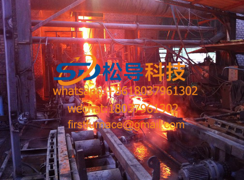
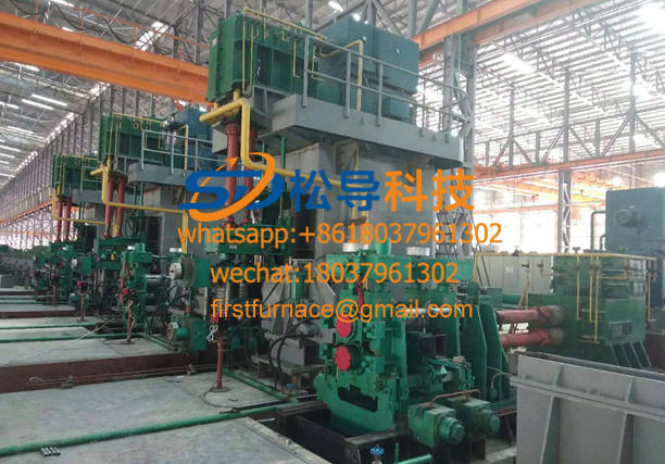
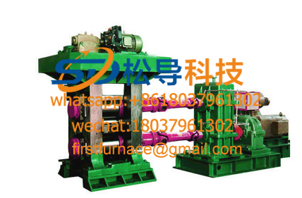
8. A set of continuous rolling mills
1). Type : three-roll Y -type
2) rod diameter: Φ9.5mm, Φ12mm, Φ15mm
3) the frame number: 15, 13
4). Roll nominal size: Φ255mm
5). Adjacent frame transmission ratio: 1:1.25
6). Final rolling speed: V=6.2m/s (maximum)
7). Rolling center height: 1052.5mm
8). Main motor power: 355kw (DC), 600r.pm
The rolling mill adopts active feeding, the power is output from the main transmission box, and the ingot is clamped by the cylinder, which is fed into the No. 1 frame. By the rolling mill 15 composed of Y-type three-roll rack, nominal roll diameter Φ255mm, the even-numbered gear rack is co seven odd chassis to drive a total of eight lower, left and right alternately arranged. Adopt the arc triangle one garden system hole type. The main drive uses a 355kw DC motor to transmit power through the toothed coupling and the spindle connection under the 12th subrack of the gearbox . The gear ratio between the two adjacent subracks is 1:1.25 . There is a safety toothed coupling at the joint between the gear box and the frame. When the intercept is cut, the safety pin is cut off to prevent accidents. The inlet and outlet guides are respectively arranged in front and rear of each sub-frame, the entrance position of the odd-numbered frame is rolling, and the entrance of the even-numbered frame is sliding. There is a pile detection parking device between the racks, and the rolling machine automatically stops when a putter occurs.
The side roller small arches of each rack can be adjusted by gaskets, and the tabs with different thicknesses are in the form of Huff, so that the gasket can be replaced without having to screw out all four fixing bolts. Adjustment range ±0.5mm .
The long and short shafts of the frame are designed with aluminum alloy rolling mill and copper rolling mill (Φ70mm) , high strength and long service life. The roller material is made of aluminum alloy rolling mill and copper rolling mill roll material 5CrMnMo , which has long service life.
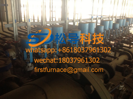
9. Rolling mill emulsion lubrication system
1). Lotion pump: IS100-65-200 Q = 80 m3/h, H=50m 15 kW 2 units ( 1 set)
2). Pressure: 0.3 - 0.5Mpa
3). Filter: GLQ-100 1 set
5). Plate heat exchanger: 35m2
The emulsion lubrication system is a two-pump system. The emulsion is divided into two via a centrifugal pump, a filter, and a heat exchanger to enter a manifold mounted on the gear box. The gears, rollers, and inlet and outlet guides of each frame are lubricated and cooled. The emulsion is passed through a return tank on the base and passed through a return line to the emulsion tank.
10. A set of rolling mill oil lubrication system
1). Gear pump: CY-18/0.36-2 5.5 kW 960r.pm 2 sets ( 1 set)
2). Working pressure: 0.1-0.3Mpa
3). Filter: GLQ-80 1 set
4). Fuel tank: 5m3
The oil supply system is a dual system. The oil in the oil tank passes through the filter through the filter to the oil inlet manifold behind the gear box, enters the gear box in three places, and then sprays the gear and the rolling bearing through the nozzle of the branch oil pipe. The oil return is from the lower side of the gear box end through the return pipe to the fuel tank.
11. A set of aluminum alloy rod quenching device
It mainly includes two sets of cooling water systems (one of which is spare) and a quenching system.
The quenching device is quenched in eight zones. The outlet of the take-up pipe is equipped with a water blowing device. The cooling medium is the circulating water of the casting machine, including the inlet and outlet pipes and valves.
11.1 cooling water temperature ≤ 35 ° C
11.2 Cooling water pressure 0.3-0.5MPA
11.3 quenching section length 6000mm
11.4 Temperature after quenching <100°C
12. Set of closing machine
The machine is mainly composed of an operation platform, a pinch device, an approach bridge, a circular cycloidal device, a storage line device, a trolley, and the like.
12.1 traction device
12.1.1 Traction speed 8.9m / s (maximum)
12.1.2 traction motor 7.5kw (AC variable frequency speed regulation )
The device uses a double active pinch and the spring adjusts the pressure. The pinch roller is driven by the AC motor through the V-belt drive, and the other pinch rollers are synchronously rotated by the two pairs of gears.
12.2 winding device
12.2.1 Ring diameter Φ2300mm
12.2.2 4kw around the rod motor (AC variable frequency speed regulation )
The aluminum alloy rod penetrates into the worm gear shaft under the traction thrust, and then pre-deforms under the spiral swing tube, and then wraps around the trolley frame.
12.3 loop car
12.3.1 Ring frame diameter Φ2300mm
12.3.2 The height of the frame is 1500mm
There are two loop frames on the trolley, and there are cylinders under the trolley, which are driven by the cylinder to realize the frame change action.
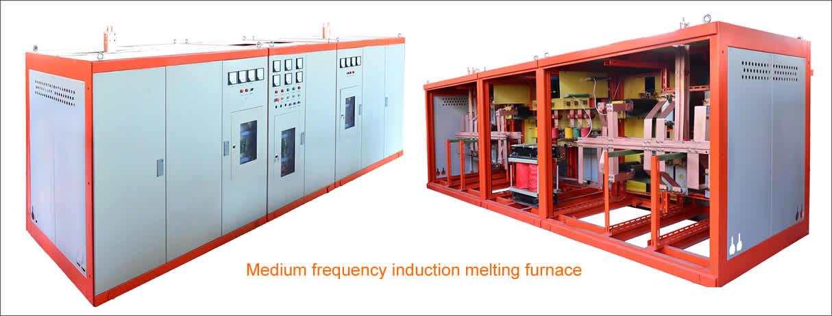
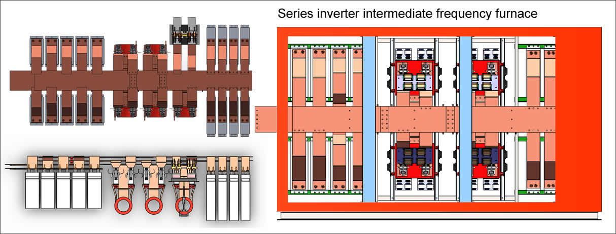
13. A set of electrical control system for continuous casting and rolling production line
The electrical system is powered by a three-phase four-wire 380V , 50Hz , low-voltage network, and the total power of the equipment is about 950kw . The transmission line of the continuous casting machine, rolling shearing machine, continuous rolling mill and closing device of the production line adopts full digital DC speed regulation or AC frequency conversion synchronous control. The control part adopts Siemens PLC plus touch screen to accurately and reliably command and coordinate the whole system work, and various operating parameters are centrally monitored and displayed. Among them: 355kw main motor adopts Siemens 6RA7087-6DS22 DC speed control device for control, with strong protection features and fault diagnosis function. The continuous casting machine motor, rolling shearing machine, traction device and winding rod device motor also adopt AC motor, which is controlled by Siemens AC frequency conversion speed regulating device. PLC is programmed by Siemens S7-300 . The touch screen is operated by TP27010吋 color touch screen man-machine interface. Various operating parameters are monitored and displayed centrally. Process parameters can be set, modified and displayed through man-machine interface, and fault diagnosis function is available. . Speed, current, voltage display, synchronous control and fault indication of continuous casting machine, rolling mill and tractor.
The whole process of the production line is full animation and visual display. At the same time, it has animation system of branch subsystem such as cooling system, lubrication system and blocking alarm. It can easily issue operation instructions and check the running status of the equipment. At the same time, the system gives an abnormal indication to the current and motor speed, and the automatic rolling alarm is automatically blocked and automatically stopped. The system's main low-voltage electrical components intermediate relays, AC contactors, air switches 32A below the Siemens product line or Schneider products, 32A or more select domestic well-known brand products. The electronic control part adopts 4 +3 counter combination: 4 electric control cabinets are integrated, connected through the base, and the appearance is beautiful, which is convenient for internal cable connection. The part of the electric control cabinet should be placed in a dedicated power distribution room, and only the casting machine and the rolling mill and the winding machine operating table should be placed at the production site.
Copyright© 2007-2013 NO.6 Electric Mall All Rights Reserved